DIY non invasive temperature gauge probe placement ideas...

Technical questions and answers about the Mazda Bongo

Moderators: Doone, westonwarrior

jaylee
Supreme Being
Posts: 5500
Joined: Wed Mar 05, 2008 4:56 pm
Location: AQVAE SVLIS

Re: DIY non invasive temperature gauge probe placement ideas

Post by jaylee » Tue Aug 30, 2011 9:11 am

bikerbob wrote:Yes thats exactly how my sensor probes react, ambient temperature then climb as coolant heats up but on reaching temps of +75C and above erratic temp readings occur.

Is the metal heater hose the long one that runs along the top of the head and is about 25mm Dia above the head of
the rubber hose metal spigot, if so can fit 2nd sensor probe on there. The vehicle is a 2.5TD year 1997/98.
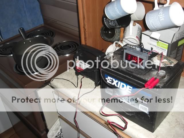
Right, sounds like we have the same motor Bob.. Mines a 95.

I fitted the first probe to part 15-179, on the stub.. http://lushprojects.com/bongopartsmk2/c ... mgno=.html Which is shielded from the front by the cam belt casing/enclosure..

The other probe.. Is the heater outlet spigot, drivers side... (Just above the rad fan sensor.)
Check the link on the second post down on this topic about leaks..! http://www.igmaynard.co.uk/bongo/forum/ ... +hose+leak

Here's a rough drawing... (Its a tight space & i used a metal zip tie holding it in place on the spigot.)

Image

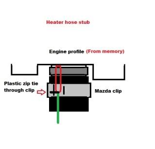
First chance i get, i will do a photo shoot of my own... :wink:
Cheaper by comparison to a race horse...
Image
tallbongo
Bongolier
Posts: 396
Joined: Sat Jul 31, 2010 5:40 pm
Location: Central Scotland

Re: DIY non invasive temperature gauge probe placement ideas

Post by tallbongo » Tue Aug 30, 2011 7:57 pm

bikerbob wrote:On saturday fitted a digital thermometer supplied by Sure Electronics. Red wire hooked up from live radio link,black ground wire earthed to metal part of radio(did check wiring continuity),sensor 1 secured onto rubber hose by plastic tie-sensor 2 secured by "Jubilee clip" :oops: onto metal stub that hose connects to, as per the photos in previous links. Everything fired up ok both sensors giving out same reading when switching between channels.
Started engine & watched the channel readouts as the engine warmed up, the rubber hose readings were significantly lower than that of the metal stub, everything ok until the readout of the metal stub hit 75C then erratic readings occurred, as the coolant got hotter the readouts began to flash between the higher temp figure & minus temp of 45C :? :? the readings from the hose were stable at 75C.
Decided on road testing-the metal stub readout hit 89C the hose readout 78C both readouts now wildly fluctuating, stopped vehicle & turned off engine, started up again & on return journey notice that readout temperatures dropped lower, presumed that this was due to airflow over the sensors from the fans ???.
Sent email to Sure via ebay explaining the above, also complained that the connection wires were too short & had to be extended also the sensor leads appeared to be shorter than those depicted in photo on the ebay listing thus causing installation difficulties.
The response today from my email was that the above comments have been put to the technical department for an opinion & will respond in 48hours. Apologies for the length of the Tome. :roll: :roll:
This concerned me so lacking a Bongo to fit it to at the moment, I ran a crude experiment on my Sure sensor. It doesn't look as if the sensor is fit for purpose.

First the setup. Both probes connected to the outside of a pan containing water. Power supply was an old car battery connected to a charger giving a 12.07V supply voltage (measured before and after trial). The cooker was turned on to heat up the pan.

Image

The temperatures measured as below. Every temperature above 70 deg C was incredibly difficult to determine due to garbling of the display as described by bikerbob (at one point it read -50 deg C). You can see that throughout most of the experiment Ch1 read significantly above Ch2 despite only being an inch apart. So the reading for 30 mins was taken seconds after that of 29 mins reading, but with the probes' input channels swapped over. this shows it is the probes at fault for the offset.

Image

At about 80 deg C I gave up trying to read the display and added cold water to the pan to accelerate its cooling.

I'm emailing the seller detailing the problems.
95 N Reg 4WD Manual AFT Bongo

Image Image
User avatar
haydn callow
Supreme Being
Posts: 5777
Joined: Mon Jan 08, 2007 9:50 pm
Location: Somerset
Contact:

Re: DIY non invasive temperature gauge probe placement ideas

Post by haydn callow » Tue Aug 30, 2011 8:01 pm

As I pointed out some time ago.......you tend to get what you pay for..
http://www.coolantalarm.co.uk
Developer of the Mazda Bongo Coolant loss Alarm
Also BMW Clocks
tallbongo
Bongolier
Posts: 396
Joined: Sat Jul 31, 2010 5:40 pm
Location: Central Scotland

Re: DIY non invasive temperature gauge probe placement ideas

Post by tallbongo » Tue Aug 30, 2011 8:08 pm

I hope the seller has a more constructive response. I only hope to get what is advertised.
95 N Reg 4WD Manual AFT Bongo

Image Image
nigelgibson
Tribal Elder
Posts: 652
Joined: Fri Aug 06, 2010 1:33 pm
Location: n.e. derbyshire

Re: DIY non invasive temperature gauge probe placement ideas

Post by nigelgibson » Tue Aug 30, 2011 8:13 pm

thinking out loud - is the paper clip holding sensor in place on pan a good enough connection to give consistant read outs ?

jaylee's jubilee clip is likely to give better fit and conduct heat better isn't it ?
User avatar
missfixit70
Supreme Being
Posts: 12431
Joined: Fri Jun 01, 2007 3:53 pm
Location: weymouth

Re: DIY non invasive temperature gauge probe placement ideas

Post by missfixit70 » Tue Aug 30, 2011 8:18 pm

or clip the two probes together & ensure they are in contact with the surface to be measured to exactly the same degree so you know they are reading EXACTLY the same, as you are doing a comparative test.
You can't polish a turd - but you can roll it in glitter.
tallbongo
Bongolier
Posts: 396
Joined: Sat Jul 31, 2010 5:40 pm
Location: Central Scotland

Re: DIY non invasive temperature gauge probe placement ideas

Post by tallbongo » Tue Aug 30, 2011 8:21 pm

Undoubtedly a jubilee clip will be much more secure, but as I don't have a pot sized one I used the paperclips. I bent them so that they were holding the tip of the probes tightly against the side of the pan. The probes never moved during the experiment even when I swapped the wires over between the two channels. I did try to think of something better to secure them, but wasn't confident that any alternative lying around the house would be safe at temps up to 100 deg C.

So although I can't say there was no variation due to the connection, I can safely say that the garbled display was not due to this. Certainly neither probe ever made it to -50 deg as displayed at one point.

As two other forum members have the same problem, I think it's safe to conclude at least some of the units recently shipped are faulty.
95 N Reg 4WD Manual AFT Bongo

Image Image
nigelgibson
Tribal Elder
Posts: 652
Joined: Fri Aug 06, 2010 1:33 pm
Location: n.e. derbyshire

Re: DIY non invasive temperature gauge probe placement ideas

Post by nigelgibson » Tue Aug 30, 2011 8:25 pm

As i have one ready to fit [ still waiting for longer sensor from sure electronics] i would be interested to see how you get on. i will test mine tomorrow and report results.
tallbongo
Bongolier
Posts: 396
Joined: Sat Jul 31, 2010 5:40 pm
Location: Central Scotland

Re: DIY non invasive temperature gauge probe placement ideas

Post by tallbongo » Tue Aug 30, 2011 8:30 pm

missfixit70 wrote:or clip the two probes together & ensure they are in contact with the surface to be measured to exactly the same degree so you know they are reading EXACTLY the same, as you are doing a comparative test.

I was mainly doing a test to check the display problem bikerbob described, but I did draw a conclusion that there was an offset between the probes which may not have been fair. I've found a better way of wedging the probes together so am doing a quick re-check.
95 N Reg 4WD Manual AFT Bongo

Image Image
bikerbob

Re: DIY non invasive temperature gauge probe placement ideas

Post by bikerbob » Tue Aug 30, 2011 8:45 pm

Have received an email from sure electronics the digital thermometer seller stating that there is an error with the software and do I have a progammer!!!! & would I mind to reprogramme the item with Hex file which was sent as an attatchment to the email.the hex file is made up of numbers & letters each line is 42 characters long & the lines go on for ever, numbers at each line starting at1000 :roll: :roll: [-o< He also said would give big discount on my next purchase. :lol: :lol:

I believe he thinks I`m an auto/electronics engineer due to the fact he thought I could reprogramme it. will get back to him and I want an FOC replacement, if he does`nt play ball will threaten to report this situation to ebay as the item is not fit for purpose. I also directed him to the bongo fury website & the forum link "DIY non invasive temperature gauge probe placement ideas" don`t think his english is up to speed to understand our humour or the forum.

Interesting test tallbongo, pleased someone has verified my findings, good to know I`m not as crazy as I think I am :twisted: :twisted: Let me know the result of your complaint to Sure Electronics feel free to add my name R Nash in your email maybe he will send replacement units to us if we bitch loud enough.
nigelgibson
Tribal Elder
Posts: 652
Joined: Fri Aug 06, 2010 1:33 pm
Location: n.e. derbyshire

Re: DIY non invasive temperature gauge probe placement ideas

Post by nigelgibson » Tue Aug 30, 2011 8:52 pm

same seller that told me the probe was 3m long then sent one 1m and asked for $4 when i complained. he sent new one [ not here yet but got tracking number] when i politely told him to **** off. he offered me a discount if i would extend the 1m probe myself !
User avatar
widdowson2008
Supreme Being
Posts: 1703
Joined: Tue Nov 18, 2008 10:15 pm
Location: N.E.Derbyshire

Re: DIY non invasive temperature gauge probe placement ideas

Post by widdowson2008 » Tue Aug 30, 2011 8:54 pm

tallbongo wrote:
missfixit70 wrote:or clip the two probes together & ensure they are in contact with the surface to be measured to exactly the same degree so you know they are reading EXACTLY the same, as you are doing a comparative test.

I was mainly doing a test to check the display problem bikerbob described, but I did draw a conclusion that there was an offset between the probes which may not have been fair. I've found a better way of wedging the probes together so am doing a quick re-check.
I know they're cheap (not laboratory standard) but those figures are a bit dissapointing. Glad you are having another go and hope you have better luck this time. =D>
You mentioned in the first test that you were 'holding the tip of the probes tightly against the side of the pan'. This may be the cause of some of the error.
The sensors are 20/30mm long, so probably one source of error may be because you need to keep as much of the sensor in contact as possible. As Jamie has his strapped on with a Jubilee, his will be fairly flat I would have thought. ie:reading along its full length and not just at the tip. May be wrong, but worth considering :wink: .

This test is looking at the 2 sensos side by side - brilliant cos they need to be in sync to mean anything usefull. Could you somehow extend this experiment to include a thermometer to see how the gauge relates to real life?

Pity if Jamie got the only good one and the rest have gone South. :lol:

C'mon tallbongo - need some results man. :lol: :wink:
Steve
User avatar
Driver+Passengers
Supreme Being
Posts: 2019
Joined: Mon Mar 14, 2011 1:56 pm
Location: Fife

Re: DIY non invasive temperature gauge probe placement ideas

Post by Driver+Passengers » Tue Aug 30, 2011 9:05 pm

widdowson2008 wrote:I know they're cheap (not laboratory standard) ...
Does anyone know if the probes that come with these units are NTC thermistors or digital (DS18B20)?
Last edited by Driver+Passengers on Tue Aug 30, 2011 9:07 pm, edited 1 time in total.
Image Image
What she doesn't know won't hurt me.
tallbongo
Bongolier
Posts: 396
Joined: Sat Jul 31, 2010 5:40 pm
Location: Central Scotland

Re: DIY non invasive temperature gauge probe placement ideas

Post by tallbongo » Tue Aug 30, 2011 9:06 pm

I've redone a quick check with the probes bound together using stripped speaker cable and suspended in the water. The variation between 50 deg C and 70 deg C fluctuated between 1.0 deg C and 2.1 deg C. Given the time delay, this may just meet the spec if one probe reads as low as allowed and the other as high as allowed.

Again garbled display above 70 deg C.

Interesting reply from seller bikerbob. I've only taken the cover off to access the DIP switches but see no removable chips or cable connection points to allow reprogramming, even if it was a reasonable expectation. :!:
95 N Reg 4WD Manual AFT Bongo

Image Image
tallbongo
Bongolier
Posts: 396
Joined: Sat Jul 31, 2010 5:40 pm
Location: Central Scotland

Re: DIY non invasive temperature gauge probe placement ideas

Post by tallbongo » Tue Aug 30, 2011 9:11 pm

Regarding determining absolute temperatures, I may be able to do this at work if it is quiet, but I don't have suitable equipment at home.

Note for my revised readings in the above post, my supply battery has dropped to 8V. The difference between the two probes may well still be 3 deg C if the supply was back at 12V.
95 N Reg 4WD Manual AFT Bongo

Image Image
Post Reply

Return to “Techie Stuff”