


I converted the hex file to a binary image and ran it through IDAPro as a 16F874A which is close enough as the PICs are pretty interchangeable. If you can determine the pin designations then the code sections can be defined. The code is rather horrible though, only having 35 instructions means that it takes a load of code to perform a simple function. The easiest way to tackle this could be to write new firmware in C, are you using MPLAB IDE?
Its quite common to drive multiple 7 segment LEDs from a shared bus, if you toggle them fast enough the persistance makes it look they are driven seperately although they are a bit dimmer.
DIY non invasive temperature gauge probe placement ideas...
Moderators: Doone, westonwarrior
Re: DIY non invasive temperature gauge probe placement ideas
1995 Ford Freda, 2.5TD, auto, AFT, side conversion.
-
Driver+Passengers
- Supreme Being
- Posts: 2019
- Joined: Mon Mar 14, 2011 1:56 pm
- Location: Fife
Re: DIY non invasive temperature gauge probe placement ideas
To me, that makes it more readable!Rhinoman wrote:The code is rather horrible though, only having 35 instructions means that it takes a load of code to perform a simple function.
I agree. Downloaded MPLAB IDE a few nights ago - didn't realise it now comes with C compiler - score!Rhinoman wrote:The easiest way to tackle this could be to write new firmware in C, are you using MPLAB IDE?
Other than the alarm function, I'd like to code it such that it performs a 1-wire bus scan (potentially multiple DS18B20s per channel) and if no devices are found, falls back to ADC for NTCs. That said, make it too complicated and there's a significant challenge to design a UI that's usable!
tallbongo - might pin 11 already serve two functions?? I can't quite fathom your post-it yet.

What she doesn't know won't hurt me.
-
The Great Pretender

- Supreme Being
- Posts: 2671
- Joined: Thu Oct 19, 2006 10:10 pm
- Location: Wigan
Re: DIY non invasive temperature gauge probe placement ideas
To infinity and beyond
-
Northern Bongolow

- Supreme Being
- Posts: 7724
- Joined: Mon Mar 15, 2010 11:33 pm
- Location: AKA Vanessa
Re: DIY non invasive temperature gauge probe placement ideas
are you struggling to keep up mel-------------its easy stuff really 

-
bikerbob
Re: DIY non invasive temperature gauge probe placement ideas
Re: DIY non invasive temperature gauge probe placement ideas
Both sensors on mine (Top hose outlet & heater outlet metal stub.) Before starting the engine, read the same ambient temperature always.. (Maybe both readings a degree or two higher than the air temp due to being to the engine & covered by the van?)
My observations of this gauge also reveal at around 85c on the gauge my Mason gauge can be quite high on odd occasions (Only really going up hills) Up hill at speed however it sits a little cooler, then come down to roughly where you see the needle sat here as the gauge comes up to 91 or 92c on the top hose outlet, the heater stub about 6c lower than the leading temp..(Never any higher.)
If i stop then i let the engine idle to remove heat soak, that's when the heater hose temp joins the top hose temp (Even excelling by a degree the top hose, then they drop a little maybe to around 86/87c? Then as/if i pull away they settle back more...
So am i right in thinking the coolant is doing its job with the engine, removing the excess heat generated?
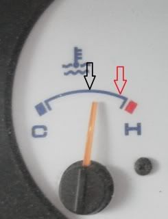
Though my fans cut in appropriately, the scav fan doesn't... (Scavs been tested & i have fitted a warning lamp to tell if it does cut in.)
Keep up the good work with the mods guys.. I've been following this with great interest!

My observations of this gauge also reveal at around 85c on the gauge my Mason gauge can be quite high on odd occasions (Only really going up hills) Up hill at speed however it sits a little cooler, then come down to roughly where you see the needle sat here as the gauge comes up to 91 or 92c on the top hose outlet, the heater stub about 6c lower than the leading temp..(Never any higher.)
If i stop then i let the engine idle to remove heat soak, that's when the heater hose temp joins the top hose temp (Even excelling by a degree the top hose, then they drop a little maybe to around 86/87c? Then as/if i pull away they settle back more...
So am i right in thinking the coolant is doing its job with the engine, removing the excess heat generated?
Though my fans cut in appropriately, the scav fan doesn't... (Scavs been tested & i have fitted a warning lamp to tell if it does cut in.)
Keep up the good work with the mods guys.. I've been following this with great interest!
Cheaper by comparison to a race horse...

Re: DIY non invasive temperature gauge probe placement ideas
The second unit still hasn't arrived yet for the dual pan test.. 
Cheaper by comparison to a race horse...
-
bikerbob
Re: DIY non invasive temperature gauge probe placement ideas
The original sure unit & sensors did give the same ambient temperature on both channels however the new unit received & using the original sensors showed a big discrepacy between them, I then connected the new sensors & same result, so this leads me to a conclusion that the new unit/sensors have not been checked for calibration, will be taking this issue up with Sure but as received new unit FOC do not think they will be too helpful.
Re: DIY non invasive temperature gauge probe placement ideas
Have a look at this Bob... http://www.igmaynard.co.uk/bongo/forum/ ... =3&t=51063bikerbob wrote:Received the new Sure unit today,
1&2 considering only utilising one channel reading off the spigot.
shoot me down in flames you technocarts if you think my reasoning is more muddled than usual.
Look forward to the responses
Cheaper by comparison to a race horse...
-
widdowson2008

- Supreme Being
- Posts: 1703
- Joined: Tue Nov 18, 2008 10:15 pm
- Location: N.E.Derbyshire
Re: DIY non invasive temperature gauge probe placement ideas
You need to be carefull using that graph as an example Jamie. Whilst valid, it only indicates what happens during the warm-up period (as explained further down in the thread).jaylee wrote:Have a look at this Bob... http://www.igmaynard.co.uk/bongo/forum/ ... =3&t=51063bikerbob wrote:Received the new Sure unit today,
1&2 considering only utilising one channel reading off the spigot.
shoot me down in flames you technocarts if you think my reasoning is more muddled than usual.
Look forward to the responses
I'm currently working on this spreadsheet which is dynamic. By changing each of the variables (of which there are more than shown - work in progress
One thing that may seem odd is that the pump outlet is not the same as the block inlet (which they should be - and in fact ARE)
Reason for this is that being dynamic, the diagram has to have a start point and I've taken this as block inlet (80) and the generated figures around the system are based on this figure. ie: the pump outlet (81.

Steve
Re: DIY non invasive temperature gauge probe placement ideas
Steve, your diagram kind of ties in with my observations of the reading of the Mason gauge & the top hose reading on the sure gauge...widdowson2008 wrote:You need to be carefull using that graph as an example Jamie. Whilst valid, it only indicates what happens during the warm-up period (as explained further down in the thread).jaylee wrote:Have a look at this Bob... http://www.igmaynard.co.uk/bongo/forum/ ... =3&t=51063bikerbob wrote:Received the new Sure unit today,
1&2 considering only utilising one channel reading off the spigot.
shoot me down in flames you technocarts if you think my reasoning is more muddled than usual.
Look forward to the responses
I'm currently working on this spreadsheet which is dynamic. By changing each of the variables (of which there are more than shown - work in progress
One thing that may seem odd is that the pump outlet is not the same as the block inlet (which they should be - and in fact ARE)
Reason for this is that being dynamic, the diagram has to have a start point and I've taken this as block inlet (80) and the generated figures around the system are based on this figure. ie: the pump outlet (81.shown is what happens as a result of that particular block inlet (80)with the variables set as shown. Sorry
At least what i was trying to explain on the earlier post??!!
If i am looking at the work in progress right?jaylee wrote:Both sensors on mine (Top hose outlet & heater outlet metal stub.) Before starting the engine, read the same ambient temperature always.. (Maybe both readings a degree or two higher than the air temp due to being to the engine & covered by the van?)
My observations of this gauge also reveal at around 85c on the gauge my Mason gauge can be quite high on odd occasions (Only really going up hills) Up hill at speed however it sits a little cooler, then come down to roughly where you see the needle sat here as the gauge comes up to 91 or 92c on the top hose outlet, the heater stub about 6c lower than the leading temp..(Never any higher.)
If i stop then i let the engine idle to remove heat soak, that's when the heater hose temp joins the top hose temp (Even excelling by a degree the top hose, then they drop a little maybe to around 86/87c? Then as/if i pull away they settle back more...
So am i right in thinking the coolant is doing its job with the engine, removing the excess heat generated?
Though my fans cut in appropriately, the scav fan doesn't... (Scavs been tested & i have fitted a warning lamp to tell if it does cut in.)
Keep up the good work with the mods guys.. I've been following this with great interest!
Cheaper by comparison to a race horse...
-
widdowson2008
- Supreme Being
- Posts: 1703
- Joined: Tue Nov 18, 2008 10:15 pm
- Location: N.E.Derbyshire
Re: DIY non invasive temperature gauge probe placement ideas
Hi Jamie - Yep, you're seeing it OK by my reckoning (we may both be a mile out of line of course )
Steve
Re: DIY non invasive temperature gauge probe placement ideas
Hey Steve, i don't mind if anybody wants to put me right....widdowson2008 wrote:Hi Jamie - Yep, you're seeing it OK by my reckoning (we may both be a mile out of line of course
I've found quite often before i've been "mistaken about a great many things"..

Blah blah dark side... Now witness the fire power of this fully armed & operational battle station...
(Sorry wrong thread.)
Cheaper by comparison to a race horse...
-
Driver+Passengers
- Supreme Being
- Posts: 2019
- Joined: Mon Mar 14, 2011 1:56 pm
- Location: Fife
Re: DIY non invasive temperature gauge probe placement ideas
So the three main digits are normal, and the final C/F is wired upside down. That's why in my simulator the last digit was always '3' with a missing the top segment!tallbongo wrote:I've not measured all the 7 segments... However they do seem to be reasonably consistent, but not all. The non-consistencies are probably enables and possibly the top segment you are having problems with.
The small 7-segment which only displays the sign seems to only be connected on one segment. It make sense that this is the middle segment and it is connected to pin 5. Hopefully this is consistent with your findings.
Bob - I look forward to receiving the unit. As promised, if I pimp it successfully, you are welcome to have it back! I will try not to trash it...
PS. I'm half wondering if we should split out to a 'Deconstructing the Sure Temperature Sensor' thread as it is likely to go on a bit - we've only just got started!!!
What she doesn't know won't hurt me.
Re: DIY non invasive temperature gauge probe placement ideas
Yep i agree DP!! Initially i only wanted to know where to stick a probe.... But i'm finding your input fascinating .
A 'Deconstructing the Sure Temperature Sensor' thread would be a great idea! 
A 'Deconstructing the Sure Temperature Sensor' thread would be a great idea!
Cheaper by comparison to a race horse...