


Or 1-wire sensors, configure their thresholds, and scan the 1-wire bus for alarm status. In both cases (NTCs or DS18B20s) if there are enough pins and spare program memory, then add one or preferably two sub-mini switches and it could be self-contained.Rhinoman wrote:You could store the threshold value in EEPROM and then allow the user to change it via the serial linkDriver+Passengers wrote: I'm still going to pursue the software approach, but it will mean that the threshold is pre-programmed.
Great to see that though - mightily impressed!
DIY non invasive temperature gauge probe placement ideas...
Moderators: Doone, westonwarrior
-
Driver+Passengers
- Supreme Being
- Posts: 2019
- Joined: Mon Mar 14, 2011 1:56 pm
- Location: Fife
Re: DIY non invasive temperature gauge probe placement ideas

What she doesn't know won't hurt me.
-
nigelgibson
- Tribal Elder
- Posts: 652
- Joined: Fri Aug 06, 2010 1:33 pm
- Location: n.e. derbyshire
Re: DIY non invasive temperature gauge probe placement ideas
wow - you guys are awesome ! 
science was never my strongpoint so this is wayyyyyyy over my head !
You do manage though to explain to us non techies in a manner we can understand !
93 now sounds like a good choice , i can see it's better to have a warning of imminent rather than immediate danger. i didn't realise the slow fans come in at 94 so i like the idea of the alert to keep an eye open that everything then does as it should. i now also know my mason is too high at 4.5 as it didn't trigger during start up at 97.
thats me sold !!
ps --again great work !!
-
missfixit70

- Supreme Being
- Posts: 12431
- Joined: Fri Jun 01, 2007 3:53 pm
- Location: weymouth
Re: DIY non invasive temperature gauge probe placement ideas
I think you may have misread (or I didn't word it well  ), my Mason is set to come on @94 (mebe a bit before) just before fans come on @96 degrees.
You can't polish a turd - but you can roll it in glitter.
-
nigelgibson
- Tribal Elder
- Posts: 652
- Joined: Fri Aug 06, 2010 1:33 pm
- Location: n.e. derbyshire
Re: DIY non invasive temperature gauge probe placement ideas
missfixit70 wrote:I think you may have misread (or I didn't word it well
thanks - i'm guessing your mason is set at 4 is it ?
it seems 93 ish is still a good temp for an alarm on the sure if no mason present but as i know you have a mason if you were to alarm your sure gauge [ when they send you a working one ! ] would you set it at a different level to the 93/94 you already have the mason at ?
if you would - what temp and why ?
And for tallbongo/driver will your sure gauge alarm be set at one fixed temp or will it be possible to select?
Re: DIY non invasive temperature gauge probe placement ideas
Using a 3.3V regulator to supply the voltage divider (R1,R2,R3) that sets the switching voltage, either is possible.nigelgibson wrote:missfixit70 wrote:I think you may have misread (or I didn't word it well
thanks - i'm guessing your mason is set at 4 is it ?
it seems 93 ish is still a good temp for an alarm on the sure if no mason present but as i know you have a mason if you were to alarm your sure gauge [ when they send you a working one ! ] would you set it at a different level to the 93/94 you already have the mason at ?
if you would - what temp and why ?
And for tallbongo/driver will your sure gauge alarm be set at one fixed temp or will it be possible to select?
I'd need to check at these temps, but assuming the voltage-temp relationship is accurate into the 90 -100 deg C range, using resistor values of 270K and 1.5M with a 47K potentiometer in the middle would have a range of alarm settings from 90 deg C to approx 97.2 deg C, which seems a reasonable range.
Pretty much any range can be selected, but the wider the range, the more chance there is of user error by inadvertently adjusting the pot.
Alternatively you could get rid of the pot and just have a fixed alarm point.
If anyone with a working Sure fancies building this, please do and let us know how you get on.
95 N Reg 4WD Manual AFT Bongo


-
Driver+Passengers
- Supreme Being
- Posts: 2019
- Joined: Mon Mar 14, 2011 1:56 pm
- Location: Fife
Re: DIY non invasive temperature gauge probe placement ideas
Tenner says it's you...tallbongo wrote:If anyone with a working Sure fancies building this, please do and let us know how you get on.
What she doesn't know won't hurt me.
-
Driver+Passengers
- Supreme Being
- Posts: 2019
- Joined: Mon Mar 14, 2011 1:56 pm
- Location: Fife
Re: DIY non invasive temperature gauge probe placement ideas
Though I still don't have a unit to play with, I loaded up the HEX that bikerbob sent me into PIC Simulator IDE and started to get a bit more from it.Driver+Passengers wrote:I'm still going to pursue the software approach, but it will mean that the threshold is pre-programmed.
RC0:7, RA0:1, RA5 and RB7 are given over to the LED display. Pin1 is power, Pin20 is GND, and it must be using an internal oscillator. That's 14 so far, leaving six. AN2:3 and AN9:11 are configured as analog inputs (5) and RA3/MCLR is digital input.
[*] Red/Black: power
[*] Cyan/Magenta: LED enable/segments
[*] Blue: analog in
[*] Green: digital in
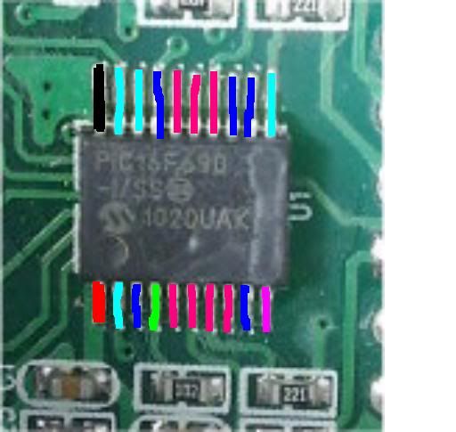
I'm a bit hazy on the precise role of each of the blue/green pins. AFAIK, inputs are light sensor, temp sensor 1, temp sensor 2, 4x DIP switches (multiplexed through resistor network?). Any filling in of the gaps here would be appreciated, or indeed a broken unit (happy waiting).
So it will be tight - but probably no reason why you couldn't for example multiplex the light sensor and buzzer onto the same pin.
[Edit: PIC datasheet here]
What she doesn't know won't hurt me.
Re: DIY non invasive temperature gauge probe placement ideas
It's a difficult board to follow with the surface mount components obscuring tracks. I tried taking photos, but either my camera or photography skill is not up to it. It may not have helped anyway as I suspect it may be a 4 layer board as the CH2 input appears to go across R18 and C11 (in parallel and connected to the ground plate) then onto a dead end, with nothing on the other side of the board.
The only one of the blue or green pins I can trace is pin 13 which seems to go through a resistor to the middle 7 seg display unit.
Other than that, pin 4 is very difficult to trace beyond the component you can see in your photo. The rest all appear unconnected, but may well have tracks obscured by the PIC or by the 7 segment displays on the other side. You are aware there are 4 7 segment displays?
I'm not sure that the LDR uses an input - I think the brightness may be controlled by an analogue circuit. It appears to go through a resistor straight to one of the 7 segments.
Sorry it's not much help, but it's the best I can do at the moment. I may have a bash with a multimeter later.
What form do you have the code in? Please don't say assembler!
95 N Reg 4WD Manual AFT Bongo
-
Driver+Passengers
- Supreme Being
- Posts: 2019
- Joined: Mon Mar 14, 2011 1:56 pm
- Location: Fife
Re: DIY non invasive temperature gauge probe placement ideas
Thanks for having starting this - some interesting points there to note. Pending success with bikerbob's replacement, I may be getting hold of a unit shortly. (Cheers, Bob).tallbongo wrote:It's a difficult board to follow...
The segment/decimal-point lines I believe are shared between all digits, with individual enable bits for each digit. (In my simulator, there appears to be some sort of anomaly with the second channel (?) where it enables two of the digits simultaneously. Or maybe I've got pin assignments wrong. What's worse though, is that it clears the segment lines before the enable lines, which means the simulator can't latch the digits as it thinks they're actually cleared. But basically, each digit is strobed in turn and persistence of vision makes them appear constant.
.hex! You need to disassemble before getting the assembly listing!!tallbongo wrote:What form do you have the code in? Please don't say assembler!
Do you have an understanding of what each of the dip switches do?
What she doesn't know won't hurt me.
-
bikerbob
Re: DIY non invasive temperature gauge probe placement ideas
Received the new Sure unit today, wired in using existing in situ kit from previous unit, at ambient temperature engine cold, sensor 1 on spigot & sensor 2 on rubber hose there was a 15C reading difference between channel 1&2, decided to try new `3METRE length`sensors plugged into unit but with sensors draped over the steering wheel, ambient reading difference similar which suggests that the unit/sensors have not been calibrated to read same. Road tested the system and everything seems to be working ok apart from the calibration issue, can live with this as I only want to know if & when an overheat situation commences, max temperature recorded on 20 mile road test and at idleing speeds 91C(at spigot) anything above this would investigate header tank level for coolant loss. Due to the difference between channels
1&2 considering only utilising one channel reading off the spigot.
shoot me down in flames you technocarts if you think my reasoning is more muddled than usual.
Look forward to the responses
1&2 considering only utilising one channel reading off the spigot.
shoot me down in flames you technocarts if you think my reasoning is more muddled than usual.
Look forward to the responses
Re: DIY non invasive temperature gauge probe placement ideas
Excellent, hopefully I'll get mine soon too then.
Started checking board with multi meter. Findings so far
7 seg displays – commoned as suggested.
Pin 1 Vcc+
Pin 2 - can't find any connection to 7-segs.
Pin 3, 4 high resistance connection to DIPs - changes upon switch position, but not in a binary manner (still investigating)
Pins 5, 6, 7, 8 7 seg displays (through 220 ohm)
Pin 9
Pin 10
Pin 11
Pin 12
Pin 13 Ch1
Pins 14, 15 and 16 7 seg displays (through 220 ohm)
Pin 17 Ch2
Pin 18
Pin 19
Pin 20 Gnd
95 N Reg 4WD Manual AFT Bongo
-
Driver+Passengers
- Supreme Being
- Posts: 2019
- Joined: Mon Mar 14, 2011 1:56 pm
- Location: Fife
Re: DIY non invasive temperature gauge probe placement ideas
Great!
(this thread hasn't half taken some twists and turns - and all over something less than a few cubic inches!)
Are the same segments commoned in each case? I'm finding the top horizontal on the last digit a bit peculiar... also I think pin 11 is the decimal point. I claim the LED enable pins are in the following order (according to display digits): 19 2 18 10. If you probe any more, I'd be interested to know if/how I'm wrong on any of this.tallbongo wrote:7 seg displays – commoned as suggested.
Whatever is on pin 12, appears to kick it all off - immediately after turning on, I get no LED display until I apply some non-zero voltage to pin 12.tallbongo wrote:Pin 12
(this thread hasn't half taken some twists and turns - and all over something less than a few cubic inches!
What she doesn't know won't hurt me.
Re: DIY non invasive temperature gauge probe placement ideas
Driver+Passengers wrote:
RC0:7, RA0:1, RA5 and RB7 are given over to the LED display. Pin1 is power, Pin20 is GND, and it must be using an internal oscillator. That's 14 so far, leaving six. AN2:3 and AN9:11 are configured as analog inputs (5) and RA3/MCLR is digital input.
[*] Red/Black: power
[*] Cyan/Magenta: LED enable/segments
[*] Blue: analog in
[*] Green: digital in
I'm a bit confused by this and your latest post where you claim pins 2, 10, 18 and 19 are the enables. I think 10 should be cyan and 11 some other colour - it's connected to the LDR.
Anyway here's an update.
7 seg displays – commoned as suggested.
Pin 1 Vcc+
Pin 2 – no connection <200K to any 7-seg pin
Pin 3 Dip 1,2,3,4 – see below
Pin 4 Dip 1,2,3,4 – see below
Pins 5, 6, 7, 8 7 seg displays (through 220 ohm)
Pin 9 – Dip 3,4
Pin 10
Pin 11 - LDR through a 7K resistance.
Pin 12 Dip 1,2
Pin 13 Ch1
Pins 14, 15 and 16 7 seg displays (through 220 ohm)
Pin 17 Ch2
Pin 18 - no connection <200K to any 7-seg pin
Pin 19
Pin 20 Gnd
DIP switches 1,2 commoned
Both On – 6K to pin 3, 15K to pin 4
1 on, 2 off 7K and 16K
1 off, 2 on 7K and 16K
Both off – 14K and 21K
Dip switches 3,4 commoned
Both On – 6K to pin 3, 15K to pin 4
1 on, 2 off – 8K and 17K
1 off, 2 on - 7K and16K
Both off - 12.8K and 20.6K
(all resistances approximate as they are hard to measure on such closely grouped pins)
I've not measured all the 7 segments – 10 pins on each giving (10x10x10x10) is a lot of combinations! However they do seem to be reasonably consistent, but not all. The non-consistencies are probably enables and possibly the top segment you are having problems with.
The small 7-segment which only displays the sign seems to only be connected on one segment. It make sense that this is the middle segment and it is connected to pin 5. Hopefully this is consistent with your findings.
Assuming 2, 10, 18 and 19 are the 7 seg enables and are only connected when powered up, this agrees pretty well with the coding.
The only mystery is pins 3 and 4 - clearly related to the DIPs and hopefully the code will help out here.
95 N Reg 4WD Manual AFT Bongo
-
Driver+Passengers
- Supreme Being
- Posts: 2019
- Joined: Mon Mar 14, 2011 1:56 pm
- Location: Fife
Re: DIY non invasive temperature gauge probe placement ideas
The enable pins probably go to the transistors. If LDR is through 7K, to which pin is the 7K/LDR junction attached? I'm assuming its a voltage divider read by analog pin, and energised by a digital output pin.
With that many pins used for the dips, I think we're on to a winner!
With that many pins used for the dips, I think we're on to a winner!
What she doesn't know won't hurt me.
Re: DIY non invasive temperature gauge probe placement ideas
Driver+Passengers wrote:The enable pins probably go to the transistors. If LDR is through 7K, to which pin is the 7K/LDR junction attached? I'm assuming its a voltage divider read by analog pin, and energised by a digital output pin.
With that many pins used for the dips, I think we're on to a winner!

95 N Reg 4WD Manual AFT Bongo