


In reply to Kirsty did not have to send photo`s nor were any requested, after my complaint they informed me of a software error and would send a replacement unit, I did suggest they look on the Bongo Fury website and to the link but whether they looked is unknown.
I was polite and courteous in my correspondence with them via ebay and have kept all the messagages just in case I have to escalate to a negative feedback situation, persevere and try again.
Have been advised by Sure that the item has been despatched but with customs delays expect will receive it end next week. if tallbongo,myself and you do not get a result Suggest a `class` action against Sure via ebay & paypal.
Hope the above helps.
DIY non invasive temperature gauge probe placement ideas...
Moderators: Doone, westonwarrior
-
missfixit70

- Supreme Being
- Posts: 12431
- Joined: Fri Jun 01, 2007 3:53 pm
- Location: weymouth
Re: DIY non invasive temperature gauge probe placement ideas
I kept my comms polite this time, pointing out that I knew that they knew there was an issue, I'd already sent them a pic of the broken internals on one of them aswell 
Shame really as I think this will put most people off using them again that read this thread.
Some of these cheaper type units can & do work fine, but as has already been said, there seems to be a quality control issue & now there seems to be an atttitude issue with these guys.
Shame really as I think this will put most people off using them again that read this thread.
Some of these cheaper type units can & do work fine, but as has already been said, there seems to be a quality control issue & now there seems to be an atttitude issue with these guys.
You can't polish a turd - but you can roll it in glitter.

Re: DIY non invasive temperature gauge probe placement ideas
My full time job is working with and visiting Chinese factories to carry out evaluations and QC, they make that little profit that if they can getaway with anything they will try it !
I have seen Chinese QC departments putting a "QC Passed" sticker on empty units before assembly, boxing them up ready to be shipped...never seen a QC test in its life ! Not saying they are all like this but most are, I think the saying is "you get what you pay for"
Although I have one of these temp gauges myself and it works fine, luck of the draw I guess ?
-
missfixit70
- Supreme Being
- Posts: 12431
- Joined: Fri Jun 01, 2007 3:53 pm
- Location: weymouth
Re: DIY non invasive temperature gauge probe placement ideas
Had a reply from Sure Electronics
My last reply to them - not quite so polite.....
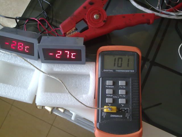
At the beginning, orange meter/gauge on the right reads correctly, all within a degree or so

Kettle boiling & apparantly it's nearly -30 degrees C.
Having already just sent pictures of the units being tested again (as anyone that knows me realises - I do not respond well to even a hint of being called a liar) Now they want me to do their QC testing???!!!!!Thanks a lot for your letter.
The reason we asked the picture is that some meters we sent to our customers are ok while the others exist problem.
It is also the requirement for us to do the daily work, hope you may understand.
Well, we can resend you a new one within 48 hours and please check it carefully.
The picture is not needed for you.
May you have a nice day.
Feel free to contact us if you have any questions.
Best wishes
Sure Electronics
My last reply to them - not quite so polite.....
At the beginning, orange meter/gauge on the right reads correctly, all within a degree or so
Kettle boiling & apparantly it's nearly -30 degrees C.
You can't polish a turd - but you can roll it in glitter.
Re: DIY non invasive temperature gauge probe placement ideas
Don't beat around the bush with a reply Kirsty....
Send em this...!
I also do greeting cards..
Send em this...!
I also do greeting cards..
Cheaper by comparison to a race horse...

-
Driver+Passengers
- Supreme Being
- Posts: 2019
- Joined: Mon Mar 14, 2011 1:56 pm
- Location: Fife
Re: DIY non invasive temperature gauge probe placement ideas
Sweet!jaylee wrote:Don't beat around the bush with a reply Kirsty....
Send em this...!
I also do greeting cards..

What she doesn't know won't hurt me.
-
missfixit70
- Supreme Being
- Posts: 12431
- Joined: Fri Jun 01, 2007 3:53 pm
- Location: weymouth
Re: DIY non invasive temperature gauge probe placement ideas
Tempting 
 Although they may see it anyway if they do look at the thread
You can't polish a turd - but you can roll it in glitter.
Re: DIY non invasive temperature gauge probe placement ideas
missfixit70 wrote:Tempting
I'm pretty sure their technical department is doing all it can to sort this problem out...

...& don't worry.. I'm not breaking rule number 10 tonight!
Cheaper by comparison to a race horse...
-
Driver+Passengers
- Supreme Being
- Posts: 2019
- Joined: Mon Mar 14, 2011 1:56 pm
- Location: Fife
Re: DIY non invasive temperature gauge probe placement ideas
Could you read off the writing on the chip in the middle, there? I'm wondering if it might be possible to mod one of these to add an alarm function. It may have a spare digital output, and may be able to be reprogrammed (unless OTP or fuses blown)...missfixit70 wrote:
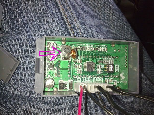
(Edit: OTP = one time programmable)
What she doesn't know won't hurt me.
-
missfixit70
- Supreme Being
- Posts: 12431
- Joined: Fri Jun 01, 2007 3:53 pm
- Location: weymouth
Re: DIY non invasive temperature gauge probe placement ideas
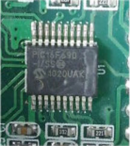
PIC16F690
-I/SS
1020UAK
I think?
You can't polish a turd - but you can roll it in glitter.
-
Driver+Passengers
- Supreme Being
- Posts: 2019
- Joined: Mon Mar 14, 2011 1:56 pm
- Location: Fife
Re: DIY non invasive temperature gauge probe placement ideas
Sweet - thanks!missfixit70 wrote:PIC16F690
If I am not mistaken, these units can use either NTC thermistors or DS18B20s. The latter could be (p)reprogrammed with desired alarm threshold - Rhinoman posted a link to a USB to 1-wire jobbie on the other thread.
What she doesn't know won't hurt me.
Re: DIY non invasive temperature gauge probe placement ideas
I was thinking of a similar mod, but done by adding a small add on board. That was one of the reasons I wanted to compare the Arduino with the Sure in person.Driver+Passengers wrote:Could you read off the writing on the chip in the middle, there? I'm wondering if it might be possible to mod one of these to add an alarm function. It may have a spare digital output, and may be able to be reprogrammed (unless OTP or fuses blown)...missfixit70 wrote:
(Edit: OTP = one time programmable)
Re-programming these should be possible given Sure's earlier reply to bikerbob (through the +5V lines the probes connect to perhaps?). However there are the disadvantages of having to totally re-code the unit (even if you provide the code, does everyone have suitable software to do this?), warranty issues and you would still have to add some minor circuitry to drive the buzzer.
On the plus side if you use the DS18B20s you could alter the alarm level fairly easily and, should a probe go faulty, you can easily replace it. No worrying about getting matching thermistors. You would also have a nice pre-built display.
When I got a working device I planned to put on an add on board with a buzzer. I would tap into the probes using a home-made Y-lead from the molex connector. One end would go to the sure device and the other the add on board, which would be something like this:

It's a very basic circuit so cheap and easy for most DIY'ers to do. I'm assuming the voltage across the NTC varies with temp and is read by an ADC in the Sure device. If not I'd have to re-think he circuit, but it will be simple.
It'll need some voltage regulator etc but I just wanted to sketch up the basics. It may also need a transistor switch if the op-amp is not suitable to drive the buzzer.
R1, R2 and R3 would be determined by taking voltage readings across the NTC at different (known) temps. This and potentiometer drift is the major downside of my suggestion vs yours.
Whatever method is chosen an alarm function should be able to be added at low cost to this device.
95 N Reg 4WD Manual AFT Bongo


-
Driver+Passengers
- Supreme Being
- Posts: 2019
- Joined: Mon Mar 14, 2011 1:56 pm
- Location: Fife
Re: DIY non invasive temperature gauge probe placement ideas
Either approach should work. Good ideas.tallbongo wrote:I was thinking of a similar mod, but done by adding a small add on board. That was one of the reasons I wanted to compare the Arduino with the Sure in person.
Re-programming these should be possible given Sure's earlier reply to bikerbob (through the +5V lines the probes connect to perhaps?). However there are the disadvantages of having to totally re-code the unit (even if you provide the code, does everyone have suitable software to do this?), warranty issues and you would still have to add some minor circuitry to drive the buzzer.
On the plus side if you use the DS18B20s you could alter the alarm level fairly easily and, should a probe go faulty, you can easily replace it. No worrying about getting matching thermistors. You would also have a nice pre-built display.
When I got a working device I planned to put on an add on board with a buzzer. I would tap into the probes using a home-made Y-lead from the molex connector. One end would go to the sure device and the other the add on board, which would be something like this:
It's a very basic circuit so cheap and easy for most DIY'ers to do. I'm assuming the voltage across the NTC varies with temp and is read by an ADC in the Sure device. If not I'd have to re-think he circuit, but it will be simple.
It'll need some voltage regulator etc but I just wanted to sketch up the basics. It may also need a transistor switch if the op-amp is not suitable to drive the buzzer.
R1, R2 and R3 would be determined by taking voltage readings across the NTC at different (known) temps. This and potentiometer drift is the major downside of my suggestion vs yours.
Whatever method is chosen an alarm function should be able to be added at low cost to this device.
What she doesn't know won't hurt me.
-
Driver+Passengers
- Supreme Being
- Posts: 2019
- Joined: Mon Mar 14, 2011 1:56 pm
- Location: Fife
Re: DIY non invasive temperature gauge probe placement ideas
Just wondering if, of the faulty Sure units received, there happens to be one which has not been requested to be returned and whose owner would consider donating to research - either now or once functioning replacement arrives? If not, I'll go buy my own but if surgery is successful, I would gladly return the pimped unit to the donor...
What she doesn't know won't hurt me.
Re: DIY non invasive temperature gauge probe placement ideas
If it's just the display you can experiment on mine. I'd like to keep the probes though.
95 N Reg 4WD Manual AFT Bongo