DIY non invasive temperature gauge probe placement ideas...

Technical questions and answers about the Mazda Bongo

Moderators: Doone, westonwarrior

tallbongo
Bongolier
Posts: 396
Joined: Sat Jul 31, 2010 5:40 pm
Location: Central Scotland

Re: DIY non invasive temperature gauge probe placement ideas

Post by tallbongo » Wed Aug 31, 2011 10:46 am

haydn callow wrote:these types of sensors are calibrated to be at their most accurate at 25C.....any error at 25C will expand as the temp rises.
i.e. 1C error at 25C will be 3C error at 75C....think I have that right.
Thermistors can be bought +/- 0.5%.......+/- 2% ect
The more accurate the more expensive.
As long as you know the error you can work it out and live with it.

It's more like a 1 deg C at 25 deg correlates to a 1.5 deg error at 75 deg C. Remember the temp is in Kelvin.
95 N Reg 4WD Manual AFT Bongo

Image Image
User avatar
haydn callow
Supreme Being
Posts: 5777
Joined: Mon Jan 08, 2007 9:50 pm
Location: Somerset
Contact:

Re: DIY non invasive temperature gauge probe placement ideas

Post by haydn callow » Wed Aug 31, 2011 12:51 pm

I thought a 5% error at 25C would also be 5% error at 75C ???

Probably not understanding it properly
http://www.coolantalarm.co.uk
Developer of the Mazda Bongo Coolant loss Alarm
Also BMW Clocks
tallbongo
Bongolier
Posts: 396
Joined: Sat Jul 31, 2010 5:40 pm
Location: Central Scotland

Re: DIY non invasive temperature gauge probe placement ideas

Post by tallbongo » Wed Aug 31, 2011 2:29 pm

haydn callow wrote:I thought a 5% error at 25C would also be 5% error at 75C ???

Probably not understanding it properly
Firstly, you are probably correct in your guess that these are 10k thermistors. A quick check gives resistances around 12kohm in our office in chilly Scotland, so room temp is at best 20 deg C.

I should make it clear that although I have had to deal with some temperature monitoring, I am not an expert - I’m a physicist/electronic engineer who’s picked most of this up from a quick read last night after my concerns raised by my experiment. If there are any experts out there I’d be delighted to be corrected as I’d like to understand this better. However, this shouldn’t be drastically wrong!


Thermistors vary their resistance with temperature. Their tolerance is specified as such, normally at 25 deg C. So a 10% 10k thermistors should be between 9kohm and 11kohm at 25 deg C.
They are highly non-linear so not the best suited to temperature critical monitoring (use thermocouples instead), but they are perfectly capable where high degrees of accuracy are not required.
I just did a quick google and plugged the first set of specs I found (for a 10k thermistor – http://www.thermistor.com/references/St ... or_QTI.pdf) into excel to produce this chart. It shows the change in resistance with temperature.

Image

There are several relationships of differing complexity used to convert resistance back to temperature. I’m using the best I could find – the 4-coefficient Steinhart-Hart. It’s very possible that the Sure device uses the B-parameter conversion as the B-parameter is more readily quoted.

Steinhart-Hart 1/T= A + B*ln(R) + C*ln(R)^2 + D*ln(R)^3
B-correlation 1/T==1/t+1/B*ln(R/r)

In both these T is the current temperature in degrees Kelvin and R is the current resistance.
In the S-H equation A,B,C and D are coefficients determined by analysis of the R-T plot above.
In the B-correlation the B is normally given on the data sheet. The lowercase t is the temp at which the specification is done, normally 25 deg C or 298 deg K and the r is the specified resistance at this temp.

A 10% thermistor could read up to 2.5 deg C out at 25 deg. However at -5 deg a 10% error in resistance gives a 1.8 deg C error, and at 100 deg a 3.6 deg C error.

This leads me to something I’d like clarified if anyone can – if a thermistor is specified at 10%, is it likely to be within 10% at all temperatures?

Note that a 5% thermistor is not much more expensive that a 10%.

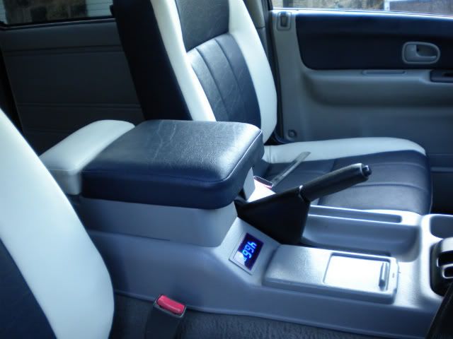
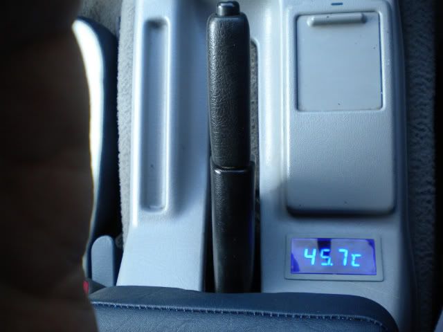
The specs for the Sure device quote +/- 1 deg C. A 5% thermistor can nearly achieve this. I’ve plotted the following chart showing the effects that a 1 deg error at 25 degrees C has at different temperatures, assuming the percentage error in resistance is constant at approx 4.5%. (I used 4220 as the B-parameter simply because the first thermistors I checked had that value).

Image

This shows that the Sure device should certainly be capable of meeting our needs, even without using expensive thermistors.

Hope this helps.
95 N Reg 4WD Manual AFT Bongo

Image Image
User avatar
haydn callow
Supreme Being
Posts: 5777
Joined: Mon Jan 08, 2007 9:50 pm
Location: Somerset
Contact:

Re: DIY non invasive temperature gauge probe placement ideas

Post by haydn callow » Wed Aug 31, 2011 2:40 pm

This leads me to something I’d like clarified if anyone can – if a thermistor is specified at 10%, is it likely to be within 10% at all temperatures?

Good questiom....
defo +/- 10% @25C

How this affected at higher temps I do not know...If it is still 10% @ 100C there could be quite a error.

As you say Thermocouples are the way to go
http://www.coolantalarm.co.uk
Developer of the Mazda Bongo Coolant loss Alarm
Also BMW Clocks
tallbongo
Bongolier
Posts: 396
Joined: Sat Jul 31, 2010 5:40 pm
Location: Central Scotland

Re: DIY non invasive temperature gauge probe placement ideas

Post by tallbongo » Wed Aug 31, 2011 4:16 pm

haydn callow wrote:This leads me to something I’d like clarified if anyone can – if a thermistor is specified at 10%, is it likely to be within 10% at all temperatures?

Good questiom....
defo +/- 10% @25C

How this affected at higher temps I do not know...If it is still 10% @ 100C there could be quite a error.

As you say Thermocouples are the way to go
No!

Rather than conjecture how about some actual figures?

Using the curve in my earlier post a +10% error at 25 deg gives a reading with an error of -2 deg C.
At 100 deg C a +10% error gives a reading with an error of -3.1 deg C.


At 25 deg C a -10% error gives a reading error of +2.2 deg C
At 100 deg C a -10% error gives a reading error of +3.5 deg C

I'm sure most people could cope with these errors especially when it is likely that a probe that reads low will continue reading low and vice versa. Taking into account the room temp errors leaves an additional error of less than 1.5 degrees.

This does depend on the actual spec of the probe, but these values were typical. The B values I quoted were from the cheapest +/-10% thermistor I looked at.

Having done some actual research, my only concern about the probe capability is if the percentage resistance deviation increases at higher temps. Even so, if at 100% the +10% error increases to +20% then the error in the reading is +7.5 deg C (2.2 deg C of which is present at room temp).

Jaylee has sourced a potential temp monitoring solution for under a tenner. This could save many Bongo heads and we should be trying to get this to work.

(edited to take the last frustrated couple of words out!)
95 N Reg 4WD Manual AFT Bongo

Image Image
User avatar
widdowson2008
Supreme Being
Posts: 1703
Joined: Tue Nov 18, 2008 10:15 pm
Location: N.E.Derbyshire

Re: DIY non invasive temperature gauge probe placement ideas

Post by widdowson2008 » Wed Aug 31, 2011 4:44 pm

tallbongo wrote: Jaylee has sourced a potential temp monitoring solution for under a tenner. This could save many Bongo heads and we should be trying to get this to work.
(edited to take the last frustrated couple of words out!)
Could not agree more. =D> Jaylee has put quite a lot of effort into this (a lot more than you see in this thread) and he should be applauded for that.
There are more accurate devices on the market (I have one) which do more than give a readout, but they come with a much heavier price tag. I hasten to add that if mine broke tomorrow, I would buy exactly the same unit.

Having said that, the Sure unit is FAR superior to this.....and remember, the one in the diagram is shown working correctly.
Image
Steve
User avatar
Driver+Passengers
Supreme Being
Posts: 2019
Joined: Mon Mar 14, 2011 1:56 pm
Location: Fife

Re: DIY non invasive temperature gauge probe placement ideas

Post by Driver+Passengers » Wed Aug 31, 2011 5:00 pm

Driver+Passengers wrote:
bikerbob wrote:... they have admitted to a software error.
That sounds promising!
The academics of the electrical/thermal properties of the sensors being used in this system is educational, and I find it really interesting - well done for the research into this. The fact that there will be some error introduced is easily tolerable, but not to be ignored. I don't think this in any way discredits the find, or that anyone is trying to. It's a steep learning curve - although not steep enough at higher temperatures it would appear! :lol: :lol: :lol: :lol:

I think the software error that the supplier has admitted to is far more relevant, in terms of identifying the cause of the "wild" values we're seeing. As for 10%, 5% or whatever, you'll soon learn to compensate in reading numbers off and know what's "normal". It can't fail to be a good thing here. I've got two-button-cell non-backlit LCD temp sensors sticky taped onto my dash purely because something is better than nothing. These cost me 99p on eBay, and I'm jealous of you guys/gals with your upmarket 12V dimmable two-probe units. I aspire to something like that!! ;)

(I'm getting some DS18B20s through from HK shortly (managed to get 20pcs @ <20p each) to pepper around the place and hook up to an Arduino. They call themselves +-0.5deg up to 85C - I've not been able to determine precisely, but I imagine these use an internal thermistor of some tolerance or other. I'll report on any progress with them in due course.)
Image Image
What she doesn't know won't hurt me.
bikerbob

Re: DIY non invasive temperature gauge probe placement ideas

Post by bikerbob » Wed Aug 31, 2011 5:48 pm

Reply to widdowson2008, did not ask for longer wired probes as thought would be pushing my luck but can live with the shorter ones.

All this technical babble has give me a headache, going down to my local wetherspoons for some fluid medication CHEERS :lol: :lol: :lol:
tallbongo
Bongolier
Posts: 396
Joined: Sat Jul 31, 2010 5:40 pm
Location: Central Scotland

Re: DIY non invasive temperature gauge probe placement ideas

Post by tallbongo » Wed Aug 31, 2011 6:29 pm

Driver+Passengers wrote:
I think the software error that the supplier has admitted to is far more relevant, in terms of identifying the cause of the "wild" values we're seeing. As for 10%, 5% or whatever, you'll soon learn to compensate in reading numbers off and know what's "normal". It can't fail to be a good thing here.

Exactly. And remember it has not been established that these probes are +/- 10%, +/- 5% or whatever. All that has been measured is that they are likely to be 10Kohm nominal resistance.

The manufacturer claims +/- 1 deg C accuracy. There is no sound reason to believe that the probes are not +/- 3% which would meet this. The retail cost is only 50p per probe more than 10%. I'm sure they are getting them massively cheaper than we can.

The only evidence that they may not meet this is the very crude test I did last night to check out if I had the display problem. I'll freely admit there is a lot of doubt over whether this was a valid trial.

However, checking out the theoretical response shows that even if they do not meet the manufacturers claims, even the cheapest thermistors would not be a disaster providing the display unit is designed with suitable care.
95 N Reg 4WD Manual AFT Bongo

Image Image
User avatar
Driver+Passengers
Supreme Being
Posts: 2019
Joined: Mon Mar 14, 2011 1:56 pm
Location: Fife

Re: DIY non invasive temperature gauge probe placement ideas

Post by Driver+Passengers » Wed Aug 31, 2011 6:49 pm

tallbongo wrote:
Driver+Passengers wrote:
I think the software error that the supplier has admitted to is far more relevant, in terms of identifying the cause of the "wild" values we're seeing. As for 10%, 5% or whatever, you'll soon learn to compensate in reading numbers off and know what's "normal". It can't fail to be a good thing here.

Exactly. And remember it has not been established that these probes are +/- 10%, +/- 5% or whatever. All that has been measured is that they are likely to be 10Kohm nominal resistance.

The manufacturer claims +/- 1 deg C accuracy. There is no sound reason to believe that the probes are not +/- 3% which would meet this. The retail cost is only 50p per probe more than 10%. I'm sure they are getting them massively cheaper than we can.

The only evidence that they may not meet this is the very crude test I did last night to check out if I had the display problem. I'll freely admit there is a lot of doubt over whether this was a valid trial.

However, checking out the theoretical response shows that even if they do not meet the manufacturers claims, even the cheapest thermistors would not be a disaster providing the display unit is designed with suitable care.
I'm with you on all of that. Presumably, an item quoting X% error more reflects the tolerance of the manufacturing process than the average performance you should expect from a part - nothing is to say a given unit may not infact read accurately. The variation in readings from a large enough sample set of thermistors probably follows a normal distribution centered around "correct" with the tails up to the quoted +- value. However this theory is still is missing the point that "accuracy" may change over the temperature range (ie non-linear). The response curve of the 10k thermistor suggests that for the temperature range we're interested in (75-100C?), we might be "better off" with a different value thermistor in order to get a steeper gradient curve in our preferred temperature range. I say "better off", but you can't get much better off than finding a cheap unit like this. Other than the software issue, should perform perfectly adequately in a Bongo.

In the end though, this is all minutiae. Sorry to chime in so late and drag the discussion off into the technicals of sensors themselves.


To end with a question, if you had 10 sensors to distribute around the van in a non-invasive way, where would you put them all? ;) Internal/external air temp, hose stubs, exhaust, etc...?
Image Image
What she doesn't know won't hurt me.
jaylee
Supreme Being
Posts: 5500
Joined: Wed Mar 05, 2008 4:56 pm
Location: AQVAE SVLIS

Re: DIY non invasive temperature gauge probe placement ideas

Post by jaylee » Wed Aug 31, 2011 8:53 pm

Driver+Passengers wrote:
To end with a question, if you had 10 sensors to distribute around the van in a non-invasive way, where would you put them all? ;) Internal/external air temp, hose stubs, exhaust, etc...?
If i could get a long enough probe wire....? I would like to monitor the temperature in my house..! :wink:
Cheaper by comparison to a race horse...
Image
User avatar
Driver+Passengers
Supreme Being
Posts: 2019
Joined: Mon Mar 14, 2011 1:56 pm
Location: Fife

Re: DIY non invasive temperature gauge probe placement ideas

Post by Driver+Passengers » Thu Sep 01, 2011 9:04 am

jaylee wrote:
Driver+Passengers wrote:
To end with a question, if you had 10 sensors to distribute around the van in a non-invasive way, where would you put them all? ;) Internal/external air temp, hose stubs, exhaust, etc...?
If i could get a long enough probe wire....? I would like to monitor the temperature in my house..! :wink:
Aye - one in each room! :roll:
Image Image
What she doesn't know won't hurt me.
tallbongo
Bongolier
Posts: 396
Joined: Sat Jul 31, 2010 5:40 pm
Location: Central Scotland

Re: DIY non invasive temperature gauge probe placement ideas

Post by tallbongo » Thu Sep 01, 2011 1:53 pm

bikerbob wrote:Result :D Received email from seller, has offered to replace the unit FOC no prompting from me but I did request that all connections & sensors be included to ensure a"clean" installation, will advise results when new unit has been insatalled.

Regarding the accuracy of the temperature read out, I`m was not too concerned with the accuracy of the temps although would be good if they were, bought the unit to inform if temps exceeded my highest normal running temp readings, perhaps I`m being nieve Haydn. How do you fit new thermisters to replace the originals and where can they be purchased fromt, as you are probably aware I`m flying by the seat of my pants on electricals etc.
I've had another 2 emails from Sure since yesterday. The first basically repeated that I'd get another gauge when they fix the problem. The second sent 8 hours later looks like delivery tracking information, although I can't get any information from the reference they gave me.

Hopefully it does mean they have fixed the problem and our replacement units will be on the way soon. If so, it's an impressive resolution to the problem (fingers crossed).
95 N Reg 4WD Manual AFT Bongo

Image Image
User avatar
widdowson2008
Supreme Being
Posts: 1703
Joined: Tue Nov 18, 2008 10:15 pm
Location: N.E.Derbyshire

Re: DIY non invasive temperature gauge probe placement ideas

Post by widdowson2008 » Thu Sep 01, 2011 4:06 pm

Went to fit Nigels (nigelgibson) Sure unit today. As Jamie has said, top hose metal stub is a b****r to fit and tighten a Jubilee clip, but a bit of Anglo Saxon helped the job along.
Was concerned that the Jubilee clip would damage the sensor as it wrapped itself around, so what I did was to tighten the Jubilee onto a 5mm screwdriver first. This 'formed' the clip and the sensor is firmly held in place. Would recommend this to anyone fitting one.

Before we fitted the sensor, we tested the rig in a kettle of boiling water to see if it was reading there or thereabouts, and it was.
Nigel has 2 sensors so we tested them side by side. Both channels 1 & 2 read correctly.

Fired the engine and watched the gauge. It did exactly what was expected. Got the reading up to mid 80's and felt the bottom hose. HOT.
So this unit seems to work fine.

Not a TM-2 which has audible alarms and a low coolant sensor (my preference if funds allow), but if funds are short, then this has got to be the next best thing. (and that is my view only - others will disagree)

Putting this big so Nigel HAS to comply. He promised me some data. :lol:
Steve
nigelgibson
Tribal Elder
Posts: 652
Joined: Fri Aug 06, 2010 1:33 pm
Location: n.e. derbyshire

Re: DIY non invasive temperature gauge probe placement ideas

Post by nigelgibson » Thu Sep 01, 2011 6:05 pm

A big thank you to Jaylee for finding this gauge and for all his work behind the scenes validating it for the benefit of all.

Likewise a big thanks also to Steve [widdowson2008 ] for his help in fitting mine today ! He did the mucky bit , fitting the probe, whilst i fitted the gauge and wired it up. Believe me i got the easy bit !

The gauge seems to be working perfectly so far but i will provide the info Steve wants to further the field test info already gathered.
Ironically after a near 3 week wait for the longer probe /sensor to arrive i fitted it in a place whereby the 1m probe was adequate.
Anyone with no space left may want to try this , a bonus being the frame of the gauge is a perfect match for the bongo grey trim.

pic 2 is view from driver's seat - i put gauge upside down as i want to read it whilst driving.


Image


Image
Post Reply

Return to “Techie Stuff”