Technical questions and answers about the Mazda Bongo
Moderators: Doone, westonwarrior
-
tallbongo
- Bongolier
- Posts: 396
- Joined: Sat Jul 31, 2010 5:40 pm
- Location: Central Scotland
Post
by tallbongo » Tue Aug 30, 2011 9:06 pm
I've redone a quick check with the probes bound together using stripped speaker cable and suspended in the water. The variation between 50 deg C and 70 deg C fluctuated between 1.0 deg C and 2.1 deg C. Given the time delay, this may just meet the spec if one probe reads as low as allowed and the other as high as allowed.
Again garbled display above 70 deg C.
Interesting reply from seller bikerbob. I've only taken the cover off to access the DIP switches but see no removable chips or cable connection points to allow reprogramming, even if it was a reasonable expectation.

95 N Reg 4WD Manual AFT Bongo


-
tallbongo
- Bongolier
- Posts: 396
- Joined: Sat Jul 31, 2010 5:40 pm
- Location: Central Scotland
Post
by tallbongo » Tue Aug 30, 2011 9:11 pm
Regarding determining absolute temperatures, I may be able to do this at work if it is quiet, but I don't have suitable equipment at home.
Note for my revised readings in the above post, my supply battery has dropped to 8V. The difference between the two probes may well still be 3 deg C if the supply was back at 12V.
95 N Reg 4WD Manual AFT Bongo
-
haydn callow
- Supreme Being
- Posts: 5778
- Joined: Mon Jan 08, 2007 9:50 pm
- Location: Somerset
-
Contact:
Post
by haydn callow » Tue Aug 30, 2011 10:20 pm
Pretty sure they are simple 10K 25C thermistors.
-
jaylee
- Supreme Being
- Posts: 5500
- Joined: Wed Mar 05, 2008 4:56 pm
- Location: AQVAE SVLIS
Post
by jaylee » Tue Aug 30, 2011 11:41 pm
tallbongo wrote:

Are these the opening/ambient temperatures on both channels at the start of the graph, Tallbongo..?
The reason i ask, is that the opening.ambient temps on both my probes strapped in two different places on the engine (one probe of which bought separately.) after the van has laid up for a couple of days.. like today both temps were 15.5c before starting the vehicle. (roughly within a fraction in keeping with the local temp.)
Cheaper by comparison to a race horse...
-
tallbongo
- Bongolier
- Posts: 396
- Joined: Sat Jul 31, 2010 5:40 pm
- Location: Central Scotland
Post
by tallbongo » Tue Aug 30, 2011 11:45 pm
The water in the pot had started heating by the time I took any readings as I was interrupted by the phone just as I was starting. So not room temp.
(edit)
I'm not worried so much by the accuracy. Even if they are 5 deg C out, as long as it is repeatable the monitor would do the job I want from it. However the garbled display was what I was testing for and I just happened to notice the offset while checking for it.
95 N Reg 4WD Manual AFT Bongo
-
jaylee
- Supreme Being
- Posts: 5500
- Joined: Wed Mar 05, 2008 4:56 pm
- Location: AQVAE SVLIS
Post
by jaylee » Wed Aug 31, 2011 12:00 am
I'm planning on running some controlled tests of my own... I certainly don't get any "garbled display" on my unit!
Would be interesting to see what reading you get if you (say for instance) taped the two probes side by side together on the work surface or frying pan, left it in place overnight, then switched the unit on...?
Cheaper by comparison to a race horse...
-
jaylee
- Supreme Being
- Posts: 5500
- Joined: Wed Mar 05, 2008 4:56 pm
- Location: AQVAE SVLIS
Post
by jaylee » Wed Aug 31, 2011 12:25 am
Just to clarify.. My initial post (Check post 1) was to find out where i could fit a probe to a cheap thermometer i took a "punt on".. After fitting, it works for me in conjunction with a Mason modded gauge, & some research finding out where the engine temp is at regarding a Mason gauge...
I like to point out, i'm not a techie... (More a Trekie!) With a red gauge read out that makes my Bongo look like a Taxi to the untrained eye..!


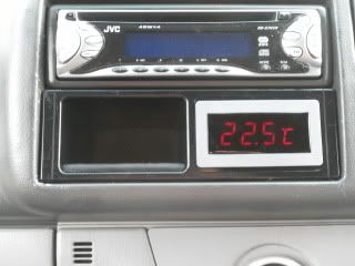
If someone knows how to get it to read in sterling, i would be grateful...

Live long... & all that!

Cheaper by comparison to a race horse...
-
bikerbob
Post
by bikerbob » Wed Aug 31, 2011 8:05 am
HI Jaylee. Regarding ambient probe temps, prior to actually fitting them onto the coolant pipes I tested the unit to make sure it worked ok, I left them in situ overnight in the vehicle dangling from the steering wheel, on viewing early am next day the readings on both channels were at the same ambient temperature of 16.8C so thats when I fitted them to the coolant pipes. As posted before, temps ok until the 75C reading then readings on both channels were garbled & showed the actual coolant temp of+89C & -45 C figures flashing between the two temps on each channel.
Will be contacting seller today to ask for replacement unit as they have admitted to a software error. will post reply if & when they respond.
-
haydn callow
- Supreme Being
- Posts: 5778
- Joined: Mon Jan 08, 2007 9:50 pm
- Location: Somerset
-
Contact:
Post
by haydn callow » Wed Aug 31, 2011 8:54 am
these types of sensors are calibrated to be at their most accurate at 25C.....any error at 25C will expand as the temp rises.
i.e. 1C error at 25C will be 3C error at 75C....think I have that right.
Thermistors can be bought +/- 0.5%.......+/- 2% ect
The more accurate the more expensive.
As long as you know the error you can work it out and live with it.
-
Driver+Passengers
- Supreme Being
- Posts: 2019
- Joined: Mon Mar 14, 2011 1:56 pm
- Location: Fife
Post
by Driver+Passengers » Wed Aug 31, 2011 9:17 am
bikerbob wrote:... they have admitted to a software error.
That sounds promising!


What she doesn't know won't hurt me.
-
jaylee
- Supreme Being
- Posts: 5500
- Joined: Wed Mar 05, 2008 4:56 pm
- Location: AQVAE SVLIS
Post
by jaylee » Wed Aug 31, 2011 9:33 am
bikerbob wrote:HI Jaylee. Regarding ambient probe temps, prior to actually fitting them onto the coolant pipes I tested the unit to make sure it worked ok, I left them in situ overnight in the vehicle dangling from the steering wheel, on viewing early am next day the readings on both channels were at the same ambient temperature of 16.8C so thats when I fitted them to the coolant pipes. As posted before, temps ok until the 75C reading then readings on both channels were garbled & showed the actual coolant temp of+89C & -45 C figures flashing between the two temps on each channel.
Will be contacting seller today to ask for replacement unit as they have admitted to a software error. will post reply if & when they respond.

Thanks Bob, I appreciate your input on this one, (Same goes for Tallbongo & Haydn Callow!)

I look forward to hearing their response...
Cheaper by comparison to a race horse...
-
bikerbob
Post
by bikerbob » Wed Aug 31, 2011 9:36 am
Result

Received email from seller, has offered to replace the unit FOC no prompting from me but I did request that all connections & sensors be included to ensure a"clean" installation, will advise results when new unit has been insatalled.
Regarding the accuracy of the temperature read out, I`m was not too concerned with the accuracy of the temps although would be good if they were, bought the unit to inform if temps exceeded my highest normal running temp readings, perhaps I`m being nieve Haydn. How do you fit new thermisters to replace the originals and where can they be purchased fromt, as you are probably aware I`m flying by the seat of my pants on electricals etc.
-
widdowson2008
- Supreme Being
- Posts: 1703
- Joined: Tue Nov 18, 2008 10:15 pm
- Location: N.E.Derbyshire
Post
by widdowson2008 » Wed Aug 31, 2011 10:04 am
bikerbob wrote:Result
Received email from seller, has offered to replace the unit FOC no prompting from me but I did request that all connections & sensors be included to ensure a"clean" installation, will advise results when new unit has been insatalled.
Regarding the accuracy of the temperature read out, I`m was not too concerned with the accuracy of the temps although would be good if they were, bought the unit to inform if temps exceeded my highest normal running temp readings, perhaps I`m being nieve Haydn. How do you fit new thermisters to replace the originals and where can they be purchased fromt, as you are probably aware I`m flying by the seat of my pants on electricals etc.
Truly a result
.
If you can get a thermometer which goes up to 100C, it would be worth doing a pan test to see how accurate the readings are. As both you and Haydn have said, it doesn't matter too much if the unit is reading high or low as long as YOU know what the true reading means.
Good on yer for persisting.
PS - have you asked for the cables to be the longer ones?
Steve
-
tallbongo
- Bongolier
- Posts: 396
- Joined: Sat Jul 31, 2010 5:40 pm
- Location: Central Scotland
Post
by tallbongo » Wed Aug 31, 2011 10:09 am
I too got a response from Sure overnight. At least they respond quickly. It reads as follows:
Dear *******,
Thanks a lot for your letter.
We apologize for the inconvenience we bring to you. We have tested the item and confirm that there is something wrong for the display.
Also we have run the test for it. After we have found the reason, we will send you the replacement. Is it ok?
Please wait for a few hours more.
Have a nice day!
It may not be the most coherent, but they have admitted there is a fault and that they will fix and send a replacement unit. I've written back confirming that if this is free of charge then it would be a very satisfactory resolution.
Fingers crossed they get their programmers doing some decent testing. Given that they sent bikerbob code, hopefully they are close to sorting this out.
95 N Reg 4WD Manual AFT Bongo
-
tallbongo
- Bongolier
- Posts: 396
- Joined: Sat Jul 31, 2010 5:40 pm
- Location: Central Scotland
Post
by tallbongo » Wed Aug 31, 2011 10:29 am
bikerbob wrote:Result
Received email from seller, has offered to replace the unit FOC no prompting from me but I did request that all connections & sensors be included to ensure a"clean" installation, will advise results when new unit has been insatalled.
Regarding the accuracy of the temperature read out, I`m was not too concerned with the accuracy of the temps although would be good if they were, bought the unit to inform if temps exceeded my highest normal running temp readings, perhaps I`m being nieve Haydn. How do you fit new thermisters to replace the originals and where can they be purchased fromt, as you are probably aware I`m flying by the seat of my pants on electricals etc.
I would imagine you have to replace with the same resistance and thermal coefficient unless you want to reprogramme the device. Thermistors are highly non-linear so I assume due to the cheapness of this device they simply match the measured resistance to a calibration curve.
I'll do a quick check on the resistance at room temp later, but to work out the thermal coefficient would take more time as I'd need to heat it up and take readings while knowing what the temperature it is at (to a high degree of accuracy).
You can get thermistors from any electrical component retailer (e.g. RS components). A 10% 10K thermistor costs about 50-60p and a 1% about £2-3.
95 N Reg 4WD Manual AFT Bongo