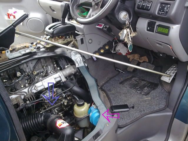
On saturday fitted a digital thermometer supplied by Sure Electronics. Red wire hooked up from live radio link,black ground wire earthed to metal part of radio(did check wiring continuity),sensor 1 secured onto rubber hose by plastic tie-sensor 2 secured by "Jubilee clip"

onto metal stub that hose connects to, as per the photos in previous links. Everything fired up ok both sensors giving out same reading when switching between channels.
Started engine & watched the channel readouts as the engine warmed up, the rubber hose readings were significantly lower than that of the metal stub, everything ok until the readout of the metal stub hit 75C then erratic readings occurred, as the coolant got hotter the readouts began to flash between the higher temp figure & minus temp of 45C

the readings from the hose were stable at 75C.
Decided on road testing-the metal stub readout hit 89C the hose readout 78C both readouts now wildly fluctuating, stopped vehicle & turned off engine, started up again & on return journey notice that readout temperatures dropped lower, presumed that this was due to airflow over the sensors from the fans ???.
Sent email to Sure via ebay explaining the above, also complained that the connection wires were too short & had to be extended also the sensor leads appeared to be shorter than those depicted in photo on the ebay listing thus causing installation difficulties.
The response today from my email was that the above comments have been put to the technical department for an opinion & will respond in 48hours. Apologies for the length of the Tome.