Page 6 of 19
Re: DIY non invasive temperature gauge probe placement ideas
Posted: Tue Aug 16, 2011 7:48 pm
by widdowson2008
tonnee wrote:Will do, at the moment my temp gauge doesnt register while driving but goes up to just under half when stopped
But will def put some reading up tomorrow once its in place
Have a look at this post. It will give you some idea of what a Mazda gauge does. An unmodified gauge is not worth the space it ocupies. (again, my opinion).
Within the post, you will see various modifications which make the Mazda gauge reading more meaningful. Personally, I think you are doing the right thing fitting a digital gauge. But if you knew me, you would know that I only believe numbers.

(sad or what
)
http://www.igmaynard.co.uk/bongo/forum/ ... azda+gauge
Re: DIY non invasive temperature gauge probe placement ideas
Posted: Wed Aug 17, 2011 9:04 am
by tonnee
Hi
Its not registering as there is no thermostat in at the mo, it does go up when stationalry though and is being sorted next week

Re: DIY non invasive temperature gauge probe placement ideas
Posted: Wed Aug 17, 2011 9:37 am
by widdowson2008
tonnee wrote:Hi
Its not registering as there is no thermostat in at the mo, it does go up when stationalry though and is being sorted next week
No thermostat? Why?
Re: DIY non invasive temperature gauge probe placement ideas
Posted: Wed Aug 17, 2011 9:38 am
by jaylee
tonnee wrote:Hi
Its not registering as there is no thermostat in at the mo, it does go up when stationalry though and is being sorted next week
Re; the other thread. Cheers for the info!!

Re: DIY non invasive temperature gauge probe placement ideas
Posted: Wed Aug 17, 2011 9:39 am
by jaylee
widdowson2008 wrote:tonnee wrote:Hi
Its not registering as there is no thermostat in at the mo, it does go up when stationalry though and is being sorted next week
No thermostat? Why?
Steve...!
http://www.igmaynard.co.uk/bongo/forum/ ... =3&t=51076
Re: DIY non invasive temperature gauge probe placement ideas
Posted: Wed Aug 17, 2011 9:39 am
by tonnee
Long storey but all on my other thread

Re: DIY non invasive temperature gauge probe placement ideas
Posted: Wed Aug 17, 2011 9:46 am
by widdowson2008
Re: DIY non invasive temperature gauge probe placement ideas
Posted: Fri Aug 19, 2011 9:22 pm
by jaylee
Just to tail end this....
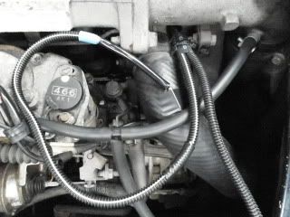
I fitted a second sensor probe to the metal heater hose stub off the engine in addition to the top hose stub sensor..
The gauge unit can be set to read two temps.. The rest of it runs back through the existing conduit with the wire from the first probe on the top hose.
So after setting it up the second sensor for a brief experiment for Steve Widdowson like this...
Thread here...
http://www.igmaynard.co.uk/bongo/forum/ ... =3&t=51063
After the temperature experiment on the rubber top hose i ran the probe wire & conduit behind the diesel pump to the heater hose stub.
I fitted the second probe to the stub on the heater outlet, which was a bit of a fiddle like this..
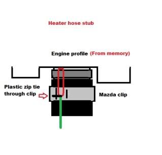
it was easier to draw than photograph clearly, there was not really much metal hose to get a purchase but it sits there nicely held in place by a 5mm wide stainless zip tie.. It was easier with the top of the air filter housing & pipe removed to get at.
Taking readings off the top hose & heater outlet....
Should help out reading temp wise with the bleeding process too!
Re: DIY non invasive temperature gauge probe placement ideas
Posted: Tue Aug 23, 2011 9:57 pm
by bikerbob
Have just received the digital temperature gauge from sure electronics. the connection wires are only 180mm in length the probe wire lengths 1metre. Looks like will have to extend the connection wires.
Being a lazy old sod could I wire a connection plug for the gauge to fit into the cigarette lighter, I can get a 2 way adaptor so could still power up my mobile or sat nav, wont look pretty but I don`t have much electrcal savvy. or can you explain in simple terms where to connect the wires to & how.
Re: DIY non invasive temperature gauge probe placement ideas
Posted: Tue Aug 23, 2011 10:27 pm
by widdowson2008
To round this off for me, these are Jaylees complete readings to 22-08-11.
Read into it what you may.
The gauge and sensor appear to be working fine. Bonus is - price is good. Still sticking to my TM-2 though.

Re: DIY non invasive temperature gauge probe placement ideas
Posted: Tue Aug 23, 2011 10:29 pm
by widdowson2008
Sorry for butting in bikerbob. Bumped your post.
bikerbob wrote:Have just received the digital temperature gauge from sure electronics. the connection wires are only 180mm in length the probe wire lengths 1metre. Looks like will have to extend the connection wires.
Being a lazy old sod could I wire a connection plug for the gauge to fit into the cigarette lighter, I can get a 2 way adaptor so could still power up my mobile or sat nav, wont look pretty but I don`t have much electrcal savvy. or can you explain in simple terms where to connect the wires to & how.
Re: DIY non invasive temperature gauge probe placement ideas
Posted: Tue Aug 23, 2011 10:46 pm
by jaylee
Yep, the live & earth wires are a little short, but i extended them...
I basically took a live feed when the ignition is on & the engine running... Fused from the blue wire with the white stripe, bottom right wire in the fuse box..
The black negative one i earthed under the dash..
The probe wires i had were 3 meters long...
I would advise anyone planning a purchase to check the spec on the unit they intend to buy...!


They can vary from a lower maximum temp reading, (mine goes up to 125c) to a shorter probe wire.. Some units specifications only allow one probe fitting... They all seem to adjust brightness to sunlight & dim so as not to glare when dark!
Hope this helps?!
Re: DIY non invasive temperature gauge probe placement ideas
Posted: Wed Aug 24, 2011 12:34 am
by The Great Pretender
widdowson2008 wrote:To round this off for me, these are Jaylees complete readings to 22-08-11.
Read into it what you may.
The gauge and sensor appear to be working fine. Bonus is - price is good. Still sticking to my TM-2 though.
Interesting, but to understand and correlate the information the bottom line should be time related. Makes it so much easier to read. 
What a quick scan shows is that the only time the stat opened was when stationary due to residual heat and not when working hard. Cooling system looks to be doing what it should.
Re: DIY non invasive temperature gauge probe placement ideas
Posted: Wed Aug 24, 2011 4:02 pm
by widdowson2008
The Great Pretender wrote:
1. Interesting, but to understand and correlate the information the bottom line should be time related. Makes it so much easier to read.
2. What a quick scan shows is that the only time the stat opened was when stationary due to residual heat and not when working hard. Cooling system looks to be doing what it should.
I originally asked Jamie to get some data to see how the gauge performed against what we already know, and it is looking quite favourable, especially the price £6.19
Jamie gave me much more info than you see on the graph, even down to his route marked on Google Earth and road names, road features, etc. but in answer to your comments:
1. Time line? I suppose I could work this out from the map and the speeds (which were quite detailed) but what will it tell us? Approx revs could also be calculated from the data. Should that be added? Graph is already looking cluttered. However, if you think there is value, ....
2. Agree with you there - stat seems to be doing exactly what it should AND at the right time.
The only thing that I queried when I graphed these results was that they are slightly different to Helens insofar as the heater circuit is concerned. Question is WHY? Could one set of data be incorrect? Knowing how both sets of data were collected, I think they are both correct. I'm currently working on correlating the 2 sets and isolating the different parameters, and the things that ARE different are the humidity and ambient temperatures. Also being very mindful that no 2 Bongos will EVER be identical for a myriad of reasons. The plot thickens but getting interesting.
Re: DIY non invasive temperature gauge probe placement ideas
Posted: Wed Aug 24, 2011 4:47 pm
by helen&tony
Hi Steve
Engine revs, speed, sampling rate, town/ country/ incline/ ambient temperature at start/ end of journey, and miles covered might show the difference. Any other difference in the data is down to age of components and driving style.
Currently, I get different readings, as most of the data collected was from a temp. range of mid-to upper 20's , from memory...currently it's "blastingly" hot. I can't reproduce any realistic data, as the route to town is almost impassable on the roads, and we have to drive on mud tracks...also, I seldom use brakes when driving...only in town...Other factors include tyres, tyre pressures/ brakes binding/ bad tracking/ worn suspension...and the only true comparison is track testing/ road testing both (or more) vehicles together, otherwise both sets have to be included, realistically speaking, and set against a known standard of a new vehicle(impossible in this case)...In the case of testing two vehicles, only a finger in the right direction is all that can be aimed for...Another point coming to mind, is the state of /age of coolant/ type of coolant, and concentration...
As long as both sets are viable, all it can show is an assumption of correct working.
Can I ask where Jay's sensors are placed, and do the figures show both in and out of the heater circuit if they differ slightly?
OOps..just editing the post
I use the air con. a lot over here, and I can see all the fans operating, so the fans will also make a difference switching in and out...the scavenger rarely shows, and the second fan never cuts in!
Cheers
Helen