


Thanks to jaylee for pointing out my error regarding sensor temp differences between spigot & rubber hose, but how do you explain similar differences when the new sensors were fitted to the unit but dangling in mid air over the steering wheel, the sensors were detecting the vehicle interior ambient temp only.
Matt your welcome to do whats necessary to the unit even if its destruct testing, hopefully you boffins can come up with a result us thickheads can understand & benefit from.
DIY non invasive temperature gauge probe placement ideas...
Moderators: Doone, westonwarrior
-
mikexgough

- Supreme Being
- Posts: 6158
- Joined: Mon Sep 08, 2008 9:02 pm
- Location: Cambridgeshire - where the all the Slodgers reside
- Contact:
Re: DIY non invasive temperature gauge probe placement ideas
The Great Pretender wrote:................Is it just me? Or would this thread be better if it was in English...............

Conversant with Bongo Top Pinion Oil Seals
Bongo owning Velotech Cycle Mechanic
Bongo owning Velotech Cycle Mechanic
Re: DIY non invasive temperature gauge probe placement ideas
mikexgough wrote:The Great Pretender wrote:
Cheaper by comparison to a race horse...


Re: DIY non invasive temperature gauge probe placement ideas
I have one on order now 
1995 Ford Freda, 2.5TD, auto, AFT, side conversion.
Re: DIY non invasive temperature gauge probe placement ideas
Yes that's correct. My earlier post about the -ve sign is wrong as I discovered while mucking around with it today. The 4th digit is smaller, used to denote C/F and the decimal point is always on (when displaying temp/not which channel) to make the degrees symbol.Driver+Passengers wrote:
So the three main digits are normal, and the final C/F is wired upside down. That's why in my simulator the last digit was always '3' with a missing the top segment!I haven't identified exactly which is the signal for the negative sign, but should be easy enough. I've traced through a great deal of the code, and have even made a couple of modifications to it running in the simulator. And found and fixed a bug (I think I introduced it). I can't quite bridge the gap from where the sensors are read to where the LEDs are output. I think there's a combination of indirect addressing and pointer arithmetic. Anyway, progress of sorts.
I can't clarify on pin 11. As far as I can see it is just used for the LDR circuit. It does look to be a strange voltage divider though (too heavily weighted to the LDR side), if that's what the circuit is.
Agreed - especially if the mods could peel out the previous posts.Driver+Passengers wrote: PS. I'm half wondering if we should split out to a 'Deconstructing the Sure Temperature Sensor' thread as it is likely to go on a bit - we've only just got started!!!. Anyone else agree?
I got my replacement today. It seems fine and as a bonus I got longer probe leads
I've built the alarm circuit and it is working with both a buzzer and LED denoting alarm conditions. The user can adjust it to alarm at any temp between 93 deg C and 103 deg C.
My previous circuit pretty much works, but if anyone else is trying it out don't use a TL071 op-amp. I think it has too low an input resistance. I'll have to investigate further, but basically I had a problem that shouldn't have happened with an ideal op-amp and swapping this out for a OP134 solved it. Unfortunately I tried just about everything else first!
I'll post more details later if I get a chance - I'm unlikely to be posting much over the forthcoming week.
95 N Reg 4WD Manual AFT Bongo


-
Driver+Passengers
- Supreme Being
- Posts: 2019
- Joined: Mon Mar 14, 2011 1:56 pm
- Location: Fife
Re: DIY non invasive temperature gauge probe placement ideas
And I now have more understanding of 16 bit arithmetic on a 8 bit MCU than I ever wanted to!!!Rhinoman wrote:I have one on order now

What she doesn't know won't hurt me.
Re: DIY non invasive temperature gauge probe placement ideas
Righty ho!!!!
Finally, the second Sure unit has been delivered....
I have a fair bit happening for the next couple of days, but i have opened the box & checked the contents....
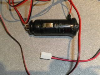
One power connector. Check.
One gauge. Check. I removed the back & there is no visible component damage!
Two X 3 meter probe cable with probe/connector on the respective end of aforementioned wire/cables... Check X2!!
All in all, so far it looks like i got what i paid for....
(I've just forgotten why i got it in the first place!)
](./images/smilies/eusa_wall.gif "Brick wall")
Finally, the second Sure unit has been delivered....
I have a fair bit happening for the next couple of days, but i have opened the box & checked the contents....
One power connector. Check.
One gauge. Check. I removed the back & there is no visible component damage!
Two X 3 meter probe cable with probe/connector on the respective end of aforementioned wire/cables... Check X2!!
All in all, so far it looks like i got what i paid for....
(I've just forgotten why i got it in the first place!)
Cheaper by comparison to a race horse...
-
widdowson2008

- Supreme Being
- Posts: 1703
- Joined: Tue Nov 18, 2008 10:15 pm
- Location: N.E.Derbyshire
Re: DIY non invasive temperature gauge probe placement ideas
Simple - you have been bitten by the 'data collection' bug - VERY addictive and no known cure.jaylee wrote: (I've just forgotten why i got it in the first place!)
Suggestion where you can fit them (after first checking them with your 'standard' - the head gauge). When Helen collected her data, she was bing to fix sensors on the ATF connections (bottom - main radiator) to check the temp difference, but she didn't have the gear at the time. As these temps affect the radiator (and hence the cooling system), they could be factored into the overall spreadsheet. Is it 'game on'?
Steve
Re: DIY non invasive temperature gauge probe placement ideas
The game is indeed afoot Steve...
I'm thinking & agree with the suggestions that this thread has gone into two directions...

There is the data collators...
... & what i am calling the "Borg collective".. They have just opened their own thread. http://www.igmaynard.co.uk/bongo/forum/ ... =3&t=51686
Now, i'm thinking that if a mod or admin works with Driver+Passengers to move the "Table napkin" idea stuff to the other thread, (Or at least duplicate it?) & keep this thread sane!??

Future references might make sense?? I have no wish hinder the the other party's great work...
I'm thinking & agree with the suggestions that this thread has gone into two directions...
There is the data collators...
... & what i am calling the "Borg collective"..
Now, i'm thinking that if a mod or admin works with Driver+Passengers to move the "Table napkin" idea stuff to the other thread, (Or at least duplicate it?) & keep this thread sane!??
Future references might make sense?? I have no wish hinder the the other party's great work...
Cheaper by comparison to a race horse...
-
mikeonb4c

- Supreme Being
- Posts: 22877
- Joined: Sun Nov 05, 2006 10:49 pm
- Location: Living with Mango Bongo in the North West but with a tendency to roam
- Contact:
Re: DIY non invasive temperature gauge probe placement ideas
I think its all great stuff. The Right Stuff.
When its done, I want it wrapped up in a nice ergonomically cool, easy to assimiliate data from, KISS (keep it simple, stupid) device that can be implemeted in my Bongo HUD. You fly fast Bongos long enough, this stuff gets to matter.

When its done, I want it wrapped up in a nice ergonomically cool, easy to assimiliate data from, KISS (keep it simple, stupid) device that can be implemeted in my Bongo HUD. You fly fast Bongos long enough, this stuff gets to matter.
Re: DIY non invasive temperature gauge probe placement ideas

Cheaper by comparison to a race horse...
-
Driver+Passengers
- Supreme Being
- Posts: 2019
- Joined: Mon Mar 14, 2011 1:56 pm
- Location: Fife
Re: DIY non invasive temperature gauge probe placement ideas
As I posted in the other thread, I can now upgrade the code on any duff units. Happy to do so FoC if you post me the unit with an SAE (or label and stamps) - just PM me. If anyone else wants the .hex file I got from Bob to upgrade their own, PM me too.
What she doesn't know won't hurt me.
Re: DIY non invasive temperature gauge probe placement ideas
Remembering why... I thought i'd set up a test today...jaylee wrote:Righty ho!!!!
Finally, the second Sure unit has been delivered....
I have a fair bit happening for the next couple of days, but i have opened the box & checked the contents....
One power connector. Check.
One gauge. Check. I removed the back & there is no visible component damage!
Two X 3 meter probe cable with probe/connector on the respective end of aforementioned wire/cables... Check X2!!
All in all, so far it looks like i got what i paid for....
(I've just forgotten why i got it in the first place!)
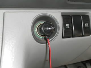
So, after soldering up the power supply for the second unit..
Then setting it up....
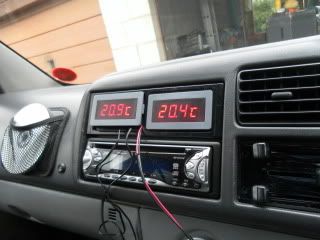
This was the opening ambient temperature on the probes on each channel on both units...
(The more astute of you may notice i have moved the gauge 1 din unit up one.. The read out adjusts to sun light & dims when dark in 3 stages.. I found a higher position was better the get the max out of this feature..)
Now, the probes on unit i have permanently fitted to the van i was somewhat limited with slack on one of the probe wires coming out of the engine bay... After unclipping what i could without completely ripping it all out..
I set it up like this...!
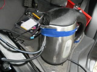
& boiled up fer coffee!
I couldn't actually get the units past 80c
So i set it like this....
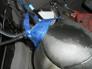
I got it to just over 90c
Tomorrow i'm gonna try boiling them in the bag.....
Cheaper by comparison to a race horse...
-
mikeonb4c
- Supreme Being
- Posts: 22877
- Joined: Sun Nov 05, 2006 10:49 pm
- Location: Living with Mango Bongo in the North West but with a tendency to roam
- Contact:
Re: DIY non invasive temperature gauge probe placement ideas
jaylee wrote:
And that's what's worrying me. Cos I'm a snot nosed fighter pilot jet jockey. Which means I don't want him after my own. I don't want his temperature gauge probe invading my placement ideas. I was thinking more that I should be doing that one, with Kelly McGillis.
Anyway guys, when's my HUD unit going to be ready for fitting - I need to be kicking the tyres and lighting the fires (well, activating me glowplugs at least)
Yrs
Chuck Jaylee
PS - forum seems crappily slow again tonite
Re: DIY non invasive temperature gauge probe placement ideas
OK so i think the last test was flawed...
Making a really strong coffee i hit on an idea.. Filling the kettle to the 1.5 litres worth i had yesterday i thought i would test the temp on the kettle the same location i taped the probes...?
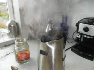
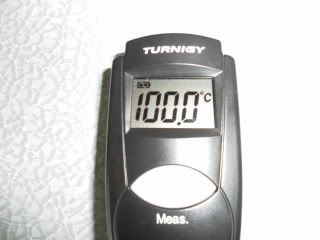
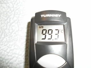
Using some black tape on the kettle, i used my Infra-red gauge to take a temperature reading at the water line.. (Infra-red scrambles on shiny surfaces like metal..?!!)
Now, realizing i had taped the four probes a little higher yesterday....!!
I took another reading in approximately the same position that the 4 probes were placed... Bearing in mind the spout is leading away a little from the boiling water line?!!
I'm off outside to take anther set of readings.... Then i'm putting the van back together.. I need it tomorrow.
Making a really strong coffee i hit on an idea.. Filling the kettle to the 1.5 litres worth i had yesterday i thought i would test the temp on the kettle the same location i taped the probes...?
Using some black tape on the kettle, i used my Infra-red gauge to take a temperature reading at the water line.. (Infra-red scrambles on shiny surfaces like metal..?!!)
Now, realizing i had taped the four probes a little higher yesterday....!!
I took another reading in approximately the same position that the 4 probes were placed... Bearing in mind the spout is leading away a little from the boiling water line?!!
I'm off outside to take anther set of readings....
Cheaper by comparison to a race horse...