


380009593474 ebay item
These are very good and if you order one the service is very good.
Cooling system
Moderators: Doone, westonwarrior
-
haydn callow

- Supreme Being
- Posts: 5778
- Joined: Mon Jan 08, 2007 9:50 pm
- Location: Somerset
- Contact:
-
alphabetter

- Bongolier
- Posts: 214
- Joined: Wed Feb 08, 2006 10:51 pm
Re: Cooling system
Aethelric your flow direction through the heating system could well be correct. To be honest the flow directions on my diagram are mostly guessed. You can get the pipe routing off the drawings, but the flows are very hard to determine unless you can measure something.
Still don't really know which pipes are connected to each other around the termostat in the "closed" and "open" positions.
Still don't really know which pipes are connected to each other around the termostat in the "closed" and "open" positions.
Re: Cooling system
Yeah I'm really just guessing there, but it seems logical. and good engineering. We'd really need to take a stat to bits to be sure of what is happening. Any ideas about the turbo?alphabetter wrote:Aethelric your flow direction through the heating system could well be correct. To be honest the flow directions on my diagram are mostly guessed. You can get the pipe routing off the drawings, but the flows are very hard to determine unless you can measure something.
Still don't really know which pipes are connected to each other around the termostat in the "closed" and "open" positions.
Your diagram is fantastic BTW
Dave
-
The Great Pretender

- Supreme Being
- Posts: 2671
- Joined: Thu Oct 19, 2006 10:10 pm
- Location: Wigan
Re: Cooling system
Grahame would it be possible to fit your sensors on the bottom pipe from the rad. One at the rad end the other at the stat end. That would enable us to find out what is happening down there.
What im thinking is when the Bongo is in traffic, stop start jam, the motor will be at tickover or around 1500 rpm max (this is when my bottom hose gets hot, within 2 miles of back to normal 30 to 40 mph driving the hose is cold). With the pump running at low speed under these conditions it is possible it is not providing enough movement of coolant, there may even be a back flow throughthe bottom hose.
Even if it flows normally in traffic im thinking that as the pump takes over at higher revs the coolant reverts back to running through the 'degassing tank'.
To infinity and beyond
-
Grahame at work
- Bongolier
- Posts: 330
- Joined: Fri Sep 30, 2005 12:43 pm
- Location: Aberdeen
Re: Cooling system
TGP I could do as you suggest.
I have decided that my experiment 1 sensor positions are not going to tell me enough. With the rate of rise of temperature and the sample/refresh rate of the two channels of the monitor I need above 4 degrees C of difference to be able to claim to detect flow direction.
SO I don't think I will be able to tell much at either end of the bottom hose.
I had been thinking this morning that I shall try across the block on the heater hoses. They have flow all the time and must transfere heat at the heater matrix so I should see a differential temperature. That would give us the flow in the heaters and from there we should be able to work out the bypass flow direction and hence the radiator flow direction.
Sounds good doesn't it - we'll see
The remarks you and others have made about the temperature of the bottom hose makes me wonder if mine does notwork the same - last night I drove home from town (4 miles) after having left Bongo parked for about 3 1/2 hours and the fans came on about a mile from home. There is no hills to speak of and little traffic - so why did they come on?
The temperature of the bottom hose as seen by my thermocouple sensor was under 20 and the Mason gauge was under 70% so I don't see why the should have come on
I may have a fault somewhere but it is not obvious as to what or where it is.
The investigation continues. I'm glad I have you lot to support me here.
Regards Grahame
Joanie2 has had a sex change and is remaned Bert
-
alphabetter
- Bongolier
- Posts: 214
- Joined: Wed Feb 08, 2006 10:51 pm
Re: Cooling system
Grahame - could you try thermometers on either side of the front heater to see if we can tell which way the water is flowing through that? That information would enable us to determine the difference between Aethelric's and my possible flow directions round the heater circuit.
Re: Cooling system
Hi Grahame. Are you sure it was the radiator fan and not a heater or aircon fan.
Good idea to measure heatdrop across heaters.
As regards the rad, I was thinking of the hose diameters. There is a large bore hose on the top hose and a large bore one on the bottom. The header tank hose is smaller bore. I would take this to mean that the main path when maximum cooling is needed is through the wide bore hoses. the scondary path through the heaters is smallaer bore.
Dave
-
dandywarhol

- Supreme Being
- Posts: 5446
- Joined: Mon Dec 19, 2005 10:18 pm
- Location: Edinburgh
Re: Cooling system
Grahame, I think you have the makings of a blocked radiator core. You could test the thermoswitch for the fans under the driver's side - the one towards the back of the head with 2 wires. Theres info on testing it in the manual. If you haven't got the figures i can find them for you.
Whale oil beef hooked
Renault Lunar Telstar
Yamaha TD1C 250, Merc SLK200, KTM Duke 690
Renault Lunar Telstar
Yamaha TD1C 250, Merc SLK200, KTM Duke 690
-
Grahame at work
- Bongolier
- Posts: 330
- Joined: Fri Sep 30, 2005 12:43 pm
- Location: Aberdeen
Re: Cooling system
Aethelric
A/C was OFF and the LED connected to the fan came on so I know it was on before I got out and checked under the bonnet when I got home.
Dandy
I had the radiator flushed when I had coolant change at the begining of the year and I have no reason to doubt the competancy of the garage.
I already have it planned to check out the sensor at the weekend although I will not take it out (don'y really want to disturbe the system until I know what I'm looking for). I want to wire up my volt meter to it so that I can monitor what it is doing in operation.
Would you agree that the fans should come on when the radiator has lost its ability to cool the fluid when the forward motion is reduced, i.e. lack of air flow through the matrix. This should mean that there is full flow through the radiator at that time and that I should be seeing a hot hose feeding the radiator and a hose returning to the engine that is increasing in temperature as the cooling effect reduces - until the fans kick in and reduce the temperature again.
Thats what I expected to find but its not what I am getting - at least not at the places I'm looking at the moment.
Regards Grahame
Joanie2 has had a sex change and is remaned Bert
Re: Cooling system
One aspect is how closely thermally coupled the sensor is to the radiator. It may be measuring a combination of the heat in the radiator and the temperature of the air flowing over the radiator. When you are stationary the sensor may reach its threshold at a lower water temperature than when you are moving. As soon as it kicks in, its as if you were moving. This may also explain why my fan comes on for short (2-3 second) bursts when stationary.Grahame at work wrote:Aethelric
A/C was OFF and the LED connected to the fan came on so I know it was on before I got out and checked under the bonnet when I got home.
Dandy
I had the radiator flushed when I had coolant change at the begining of the year and I have no reason to doubt the competancy of the garage.
I already have it planned to check out the sensor at the weekend although I will not take it out (don'y really want to disturbe the system until I know what I'm looking for). I want to wire up my volt meter to it so that I can monitor what it is doing in operation.
Would you agree that the fans should come on when the radiator has lost its ability to cool the fluid when the forward motion is reduced, i.e. lack of air flow through the matrix. This should mean that there is full flow through the radiator at that time and that I should be seeing a hot hose feeding the radiator and a hose returning to the engine that is increasing in temperature as the cooling effect reduces - until the fans kick in and reduce the temperature again.
Thats what I expected to find but its not what I am getting - at least not at the places I'm looking at the moment.
Regards Grahame
Dave
-
Grahame at work
- Bongolier
- Posts: 330
- Joined: Fri Sep 30, 2005 12:43 pm
- Location: Aberdeen
Re: Cooling system
Aethelric the sensor for the fans is mounted in the engine block/head, near the top not far from where the heater hose enters / exits under the drivers seat.
Not really thermally connected to the radiator except by way of the coolant.
Regards Grahame
Not really thermally connected to the radiator except by way of the coolant.
Regards Grahame
Joanie2 has had a sex change and is remaned Bert
-
brorabongo

- Supreme Being
- Posts: 3226
- Joined: Wed Jan 17, 2007 5:56 pm
- Location: Brora, Sutherland
Re: Cooling system
Don't know if this helps, but heres where the radiator switch is. At the bottom of the picture is the ducting for the air filter. As you can see the sensor is FUBAR, and in this condition the radiator fans came on as soon as the key was turned, and constantly ran.
It has since been replaced, thanks to Bellhill garage for the quick delivery.
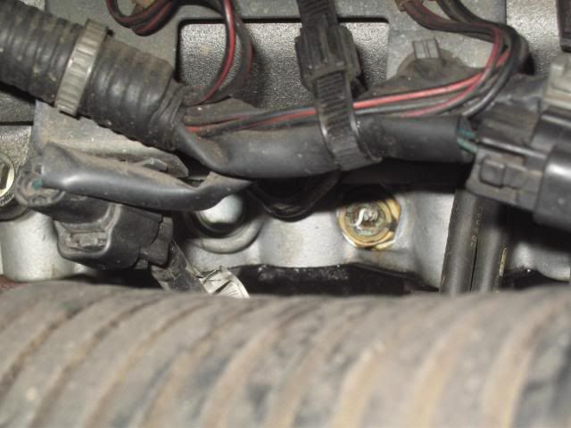
It has since been replaced, thanks to Bellhill garage for the quick delivery.
Re: Cooling system
Hmm
I wonder why mine switches on for such short bursts. There is no way that a three second blow could cool the engine down in that time. Starting to worry
Dave
I wonder why mine switches on for such short bursts. There is no way that a three second blow could cool the engine down in that time. Starting to worry
Dave
-
francophile1947
- Supreme Being
- Posts: 11354
- Joined: Mon Dec 18, 2006 6:15 pm
- Location: Norwich
Re: Cooling system
I'm no expert and, unfortunately cannot do your drawings on the computer, but I think both Aethelric's and alphabetter's diagrams are wrong.
Aethelric's show all sources flowing toward the thermostat - this surely cannot be right cos' where does the water go when the flows meet? I think alphabetter's diagram around the thermostat is more logical as it allows a continuous flow.
Both diagrams have the water flowing through the heater system in opposite directions for the front and rear heaters - how can this happen in a pumped system without causing turbulence where the contraflows meet. I believe it is more logical that the water flows in an anticlockwise direction through the rear heater and continues, in the same direction, through the front heater, thus forming a continuous flow round the circuit from the bottom of the hose from the "header/expansion" tank and back to it - at least this means that the water flows, in the same direction throughout the system.
Hope this makes sense to everyone.
Be gentle with me cos' I really don't know the answer , but it does seem more logical that all the water flows in one direction.
Aethelric's show all sources flowing toward the thermostat - this surely cannot be right cos' where does the water go when the flows meet?
Both diagrams have the water flowing through the heater system in opposite directions for the front and rear heaters - how can this happen in a pumped system without causing turbulence where the contraflows meet. I believe it is more logical that the water flows in an anticlockwise direction through the rear heater and continues, in the same direction, through the front heater, thus forming a continuous flow round the circuit from the bottom of the hose from the "header/expansion" tank and back to it - at least this means that the water flows, in the same direction throughout the system.
Hope this makes sense to everyone.
Be gentle with me cos' I really don't know the answer
John
(Evidence that intelligent life exists in the universe, is that it hasn't tried to contact us)
(Evidence that intelligent life exists in the universe, is that it hasn't tried to contact us)
Re: Cooling system
Hi Johnfrancophile1947 wrote:I'm no expert and, unfortunately cannot do your drawings on the computer, but I think both Aethelric's and alphabetter's diagrams are wrong.
Aethelric's show all sources flowing toward the thermostat - this surely cannot be right cos' where does the water go when the flows meet?
Both diagrams have the water flowing through the heater system in opposite directions for the front and rear heaters - how can this happen in a pumped system without causing turbulence where the contraflows meet. I believe it is more logical that the water flows in an anticlockwise direction through the rear heater and continues, in the same direction, through the front heater, thus forming a continuous flow round the circuit from the bottom of the hose from the "header/expansion" tank and back to it - at least this means that the water flows, in the same direction throughout the system.
Hope this makes sense to everyone.
Be gentle with me cos' I really don't know the answer
The diagram does not show the output of the thermostat, which is into the engine. Somewhere in there, the coolant meets the pump and gets pumped out of the top hose. I think the heater return flow joins up in the engine as well.
Two flows meeting are no problem, its just the opposite of one flow splitting.
We are all guessing BTW, apart from Grahame who is taking real measurements
Dave