Page 9 of 19
Re: DIY non invasive temperature gauge probe placement ideas
Posted: Fri Aug 26, 2011 1:12 pm
by jaylee
chipvan wrote:I want to try to mesure coolant temps rather than engine temps.will have to get round to fitting (in the coolant at some stage)
A fair comment Chipvan.. The non invasive method i use on the metal hose stub reason is because coolant temp heat soak reads better than through the rubber....

Which i found out after my initial query when i started this thread..
Re: DIY non invasive temperature gauge probe placement ideas
Posted: Fri Aug 26, 2011 1:18 pm
by jaylee
dave_aber wrote:I'd put mine there, but I've got front fog & spot switches there. I've got a voltmeter in the other side, and 2xblind switches below.
I'll find somewhere!
An idea Dave.. Borrowing a picture off Kirsty..
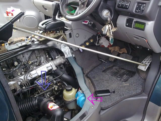
What about sort of under the cigarette lighter socket??
Re: DIY non invasive temperature gauge probe placement ideas
Posted: Fri Aug 26, 2011 1:24 pm
by dave_aber
That might be a go-er.
Where Kirsty has her green voltmeter I have also filled with the cruise control panel.
How inconsiderate of Mazda to not put enough handy wee cubby holes!
Re: DIY non invasive temperature gauge probe placement ideas
Posted: Fri Aug 26, 2011 7:40 pm
by chipvan
temps so far are not far off what my tm2 has upto 55 ish oc the temps are about 3 oc out, but when engine gets warmer say 88 ish the new display is 5- 10 oc cooler.as expected!
I expect that the cooler air passing over probe will efect this as well, my tm2 is bolted to rear of engine(where everyone else has fitted).
Iam only playing about but all the same, good fun....
Re: DIY non invasive temperature gauge probe placement ideas
Posted: Fri Aug 26, 2011 7:50 pm
by jaylee
chipvan wrote:temps so far are not far off what my tm2 has upto 55 ish oc the temps are about 3 oc out, but when engine gets warmer say 88 ish the new display is 5- 10 oc cooler.as expected!
I expect that the cooler air passing over probe will efect this as well, my tm2 is bolted to rear of engine(where everyone else has fitted).
Iam only playing about but all the same, good fun....
jaylee wrote:chipvan wrote:got mine fitted,ive got it on the top hose itself,just fixed on with a cable tie.
the display is where the spare swithces are on dash to left of steering wheel.
You maybe interested in reading this...?!! http://www.igmaynard.co.uk/bongo/forum/ ... =3&t=51063
The display placement is as good a place as any...

Remember you do by yer last post have the probe fitted to the actual top rubber hose....?!!
Mine is fitted to the metal top hose stub & shielded slightly (In theory!!) by the cam belt cover...

Re: DIY non invasive temperature gauge probe placement ideas
Posted: Fri Aug 26, 2011 7:52 pm
by chipvan
yep directly (ON) the rubber hose not in the coolant or on any metal parts
Re: DIY non invasive temperature gauge probe placement ideas
Posted: Fri Aug 26, 2011 7:54 pm
by jaylee
chipvan wrote:yep directly (ON) the rubber hose not in the coolant or on any metal parts
Me & Steve (widdowson2008) did a little test..?!!

Touch yer rubber at the same temp as yer metal....
Re: DIY non invasive temperature gauge probe placement ideas
Posted: Fri Aug 26, 2011 8:05 pm
by chipvan
was that driving along?...
great info..well done.
going to move it somewhere on metal next,
maybe on rubber is not heathly for hose...
Re: DIY non invasive temperature gauge probe placement ideas
Posted: Fri Aug 26, 2011 8:18 pm
by jaylee
chipvan wrote:was that driving along?...
great info..well done.
No, just idling on my drive...!
chipvan wrote:
Iam only playing about but all the same, good fun....
Same here Chipvan, I'm learning a fair deal as i go too!
I know its Wickepidia... but check this out too..
http://en.wikipedia.org/wiki/Thermal_conductivity (The bit about about Electrical conductivity in conjunction with thermal..?)
Re: DIY non invasive temperature gauge probe placement ideas
Posted: Fri Aug 26, 2011 8:35 pm
by chipvan
Re: DIY non invasive temperature gauge probe placement ideas
Posted: Mon Aug 29, 2011 2:56 pm
by bikerbob
On saturday fitted a digital thermometer supplied by Sure Electronics. Red wire hooked up from live radio link,black ground wire earthed to metal part of radio(did check wiring continuity),sensor 1 secured onto rubber hose by plastic tie-sensor 2 secured by "Jubilee clip"

onto metal stub that hose connects to, as per the photos in previous links. Everything fired up ok both sensors giving out same reading when switching between channels.
Started engine & watched the channel readouts as the engine warmed up, the rubber hose readings were significantly lower than that of the metal stub, everything ok until the readout of the metal stub hit 75C then erratic readings occurred, as the coolant got hotter the readouts began to flash between the higher temp figure & minus temp of 45C

the readings from the hose were stable at 75C.
Decided on road testing-the metal stub readout hit 89C the hose readout 78C both readouts now wildly fluctuating, stopped vehicle & turned off engine, started up again & on return journey notice that readout temperatures dropped lower, presumed that this was due to airflow over the sensors from the fans ???.
Sent email to Sure via ebay explaining the above, also complained that the connection wires were too short & had to be extended also the sensor leads appeared to be shorter than those depicted in photo on the ebay listing thus causing installation difficulties.
The response today from my email was that the above comments have been put to the technical department for an opinion & will respond in 48hours. Apologies for the length of the Tome.

Re: DIY non invasive temperature gauge probe placement ideas
Posted: Mon Aug 29, 2011 7:22 pm
by jaylee
bikerbob wrote:On saturday fitted a digital thermometer supplied by Sure Electronics. Red wire hooked up from live radio link,black ground wire earthed to metal part of radio(did check wiring continuity),sensor 1 secured onto rubber hose by plastic tie-sensor 2 secured by "Jubilee clip"
onto metal stub that hose connects to, as per the photos in previous links. Everything fired up ok both sensors giving out same reading when switching between channels.
Started engine & watched the channel readouts as the engine warmed up, the rubber hose readings were significantly lower than that of the metal stub, everything ok until the readout of the metal stub hit 75C then erratic readings occurred, as the coolant got hotter the readouts began to flash between the higher temp figure & minus temp of 45C
the readings from the hose were stable at 75C.
Decided on road testing-the metal stub readout hit 89C the hose readout 78C both readouts now wildly fluctuating, stopped vehicle & turned off engine, started up again & on return journey notice that readout temperatures dropped lower, presumed that this was due to airflow over the sensors from the fans ???.
Sent email to Sure via ebay explaining the above, also complained that the connection wires were too short & had to be extended also the sensor leads appeared to be shorter than those depicted in photo on the ebay listing thus causing installation difficulties.
The response today from my email was that the above comments have been put to the technical department for an opinion & will respond in 48hours. Apologies for the length of the Tome.
Did you get CH1 & CH2 between each reading Bikerbob?? Rubber hose readings will be lower than the metal stub...
Incidentally, the rubber hose fitting of the second sensor was done purely as a test.. I moved it to the metal heater outlet stub...
From what you write, sounds normal to me..?!! I might suggest repositioning the earth point under the dash to a more secure bolted area? Where the ground is mounted to the back of the radio chassis could be losing continuity with vibration from driving of the road...? Just a thought... I may have misunderstood where you grounded it??

Re: DIY non invasive temperature gauge probe placement ideas
Posted: Mon Aug 29, 2011 9:14 pm
by bikerbob
Hi jaylee,Yeah the ground was mounted on the radio chassis,but I take your point that road vibration could be an issue however the same erraticus was noticed when vehicle was stationery on my driveway with engine idleing:?
, will try to attach ground to a more stable mount. regarding the sensor locations, from the previous postings I knew that there would be a significant difference between the rubber hose & metal spigot. I did get channels 1&2 between each reading.
Am I understanding that you had both sensors on the metal spigot? if so the sensor readings on both channels should be the same. Can`t understand that the variable +&-temperature readings are a normal feature as the system is supposed to have a range from -24C to +125C. And that temperatures at 75C + were erratic & unstable. If this is normal why are SURE asking their technical bods to investigate
Why if the + tolerence level has not been approached is the unit failing at such low temperatures below +125C & why would there be a minus reading irrespective of where the sensors are located. it ain`t winter yet. I have not seen any evidence on the forum to suggest that this is acceptable performance. If you look at the temperature graphs as posted non of the figures achieve a minus reading, they are always in the plus range, som`ets up & don`t make sense to a person such as me who has been educated to above their intelligence level. If anyone can educate me in this issue would be grateful but please make it in simple terms, apologies for any tryping errots .
Regards Bob
Re: DIY non invasive temperature gauge probe placement ideas
Posted: Mon Aug 29, 2011 10:35 pm
by jaylee
bikerbob wrote:Hi jaylee,Yeah the ground was mounted on the radio chassis,but I take your point that road vibration could be an issue however the same erraticus was noticed when vehicle was stationery on my driveway with engine idleing:?
, will try to attach ground to a more stable mount. regarding the sensor locations, from the previous postings I knew that there would be a significant difference between the rubber hose & metal spigot. I did get channels 1&2 between each reading.
Am I understanding that you had both sensors on the metal spigot? if so the sensor readings on both channels should be the same. Can`t understand that the variable +&-temperature readings are a normal feature as the system is supposed to have a range from -24C to +125C. And that temperatures at 75C + were erratic & unstable. If this is normal why are SURE asking their technical bods to investigate
Why if the + tolerence level has not been approached is the unit failing at such low temperatures below +125C & why would there be a minus reading irrespective of where the sensors are located. it ain`t winter yet. I have not seen any evidence on the forum to suggest that this is acceptable performance. If you look at the temperature graphs as posted non of the figures achieve a minus reading, they are always in the plus range, som`ets up & don`t make sense to a person such as me who has been educated to above their intelligence level. If anyone can educate me in this issue would be grateful but please make it in simple terms, apologies for any tryping errots .
Regards Bob
CH1 (red line) top hose metal "spigot" CH2 (blue line) heater hose metal "spigot" While driving...(yours may vary.?)

This is a puzzle & i've had too much beer to suss out just yet...!
But i do know both my starting temps read with the ambient temp of the atmosphere & climbs & adjust with the outlet temps on the top hose outlet & heater outlet, & don't drop below zero C...
Re: DIY non invasive temperature gauge probe placement ideas
Posted: Tue Aug 30, 2011 6:33 am
by bikerbob
Yes thats exactly how my sensor probes react, ambient temperature then climb as coolant heats up but on reaching temps of +75C and above erratic temp readings occur.
Is the metal heater hose the long one that runs along the top of the head and is about 25mm Dia above the head of
the rubber hose metal spigot, if so can fit 2nd sensor probe on there. The vehicle is a 2.5TD year 1997/98.