


Hi all, I think I must have residual current drain. The LB was new in September and I fitted a Willinton kit at the same time. Had a week touring Ireland and everything was perfect even the compressor fridge never let us down. The stereo unit then was an Xtrons and most evenings we played a DVD movie which is piped through to a drop down screen and never a problem even with the volume up loud.
A couple of months back I fitted a multi function Chinese stereo head. At the time I noticed that the wiring to the Bongo's ISO connectors looked as if it had been modified so that the live was coming direct from the LB. All of the functions work great even the DTV but now, the LB is never fullly charged. The green charge indicator on the LB never shows. The fridge was removed over the winter so only the stereo is used and the Bongo does asbout 25 miles every day.
So if I now have two feeds from the LB (one via the Willinton), is this my probllem?
What would be the outcome if I changed the wiring back to the original? I assume that the head unit will then switch on and off from the ignition key and with the ignition off, it will run from the LB.
Any help wouold be very well received.
Pete
Stereo wiring
Moderator: Ian
Stereo wiring
My iPhone - My office

Re: Stereo wiring
There are two feeds for the radio, the first is (or should be) a low power feed to retain memories etc. this is a constant unswitched supply fed from this fuse;
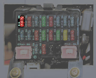
the second feed is normally a switched feed from the Ignition switch fed from this fuse, this os normally the main power circuit;
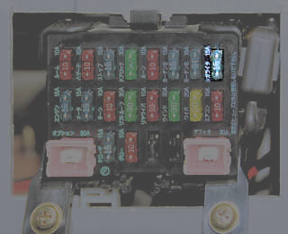
When this latter fuse is switched over to the L/B then it becomes an un-switched feed and a lot of radio's will draw an unncessary amount of power from it even when nominally "Off", one trick if this is the case is to use an additional switch to break just the radio circuit so that the radio can really be turned OFF.
the second feed is normally a switched feed from the Ignition switch fed from this fuse, this os normally the main power circuit;
When this latter fuse is switched over to the L/B then it becomes an un-switched feed and a lot of radio's will draw an unncessary amount of power from it even when nominally "Off", one trick if this is the case is to use an additional switch to break just the radio circuit so that the radio can really be turned OFF.
Geoff
2001 Aero V6, AFT, full side conversion.
2001 Aero V6, AFT, full side conversion.
Re: Stereo wiring
Thanks Geoff I will reinstate the wiring so that the head unit will switch from the ignition key and then fit a seperate switch in the wire (from the Willinton) that goes to fuse 8.
If I rember right, won't this also disable the sockets?
If I rember right, won't this also disable the sockets?
My iPhone - My office
Re: Stereo wiring
Fit the switch in the wire in the ISO adaptor on the back of the radio itself, then you won't switch everything else on the top left fuse!
Its the ISO A7 lead that needs the switch;
Its the ISO A7 lead that needs the switch;
Geoff
2001 Aero V6, AFT, full side conversion.
2001 Aero V6, AFT, full side conversion.
Re: Stereo wiring
Hi Geoff, would that be a diag of the pin layout if so is it possible to tell the colour of the wire going to ISO A7?g8dhe wrote:Its the ISO A7 lead that needs the switch;
Pete
My iPhone - My office
Re: Stereo wiring
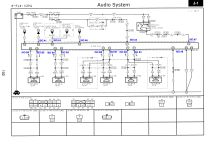
The Diagram is the circuit layout, the plug layout is in the smaller images at the bottom of the page.
The ISO numbering tells you what pin is used on the ISO adaptor itself - if you have fitted one?
The colour of the wire BEFORE the ISO adaptor is "L" for the switched power which is Blue -click the little for all the Colour Codes.
Hang on a minute just re-read that you will switch it BACK to the Ignition switch - in that case you won't want an extra switch!
Leave it on the L/B and add the extra switch in the Blue wire going to your ISO adaptor, then you can switch it really OFF when on the L/B.
The ISO numbering tells you what pin is used on the ISO adaptor itself - if you have fitted one?
The colour of the wire BEFORE the ISO adaptor is "L" for the switched power which is Blue -click the little
for all the Colour Codes.Hang on a minute just re-read that you will switch it BACK to the Ignition switch - in that case you won't want an extra switch!
Leave it on the L/B and add the extra switch in the Blue wire going to your ISO adaptor, then you can switch it really OFF when on the L/B.
Geoff
2001 Aero V6, AFT, full side conversion.
2001 Aero V6, AFT, full side conversion.
Re: Stereo wiring
[quote="]
Hang on a minute just re-read that you will switch it BACK to the Ignition switch - in that case you won't want an extra switch!
Leave it on the L/B and add the extra switch in the Blue wire going to your ISO adaptor, then you can switch it really OFF when on the L/B.[/quote]
Hi, the converter had cut a red wire and a yellow wire (within the ISO) joined them together and then joined them both to another wire going direct to the LB. I have seperated them and re-joined them with solder and to test it I removed the Willinton wire from fuse 8 put back the fuse and it would then switch the head on/off with the key.
I have now removed the fuse and replaced the W wire in fuse 8. So, if I now apply a swithch to the blue wire it will isolate the head properly right?
Below the fog light switch on the right of the panel, I have a cluster of four square blanks can one of these be utilised for the the new switch?
If so how do I get a blank out without wrecking it?
My iPhone - My office
Re: Stereo wiring
Right without ISO pin numbers it doesn't help a lot - I suspect that they linked both power feeds together and took that common point to the L/B.Hi, the converter had cut a red wire and a yellow wire (within the ISO) joined them together and then joined them both to another wire going direct to the LB. I have seperated them and re-joined them with solder and to test it I removed the Willinton wire from fuse 8 put back the fuse and it would then switch the head on/off with the key.
Yes intercept the "Blue wire" if you can within the ISO cable, it may not be Blue at that point of course! Hope that isn't to confusing!!I have now removed the fuse and replaced the W wire in fuse 8. So, if I now apply a swithch to the blue wire it will isolate the head properly right?
Yup any hole will do, the switches are held in by barbed clips top and bottom, normally a small thin screwdriver will help.Below the fog light switch on the right of the panel, I have a cluster of four square blanks can one of these be utilised for the the new switch?
If so how do I get a blank out without wrecking it?
Geoff
2001 Aero V6, AFT, full side conversion.
2001 Aero V6, AFT, full side conversion.
Re: Stereo wiring
Hi Geoff there is a blue wire next to the red and yellow wires i have re-joined - from the pin layout, can you tell if it is the right one?


My iPhone - My office
Re: Stereo wiring
That looks like the Mazda end of the Mazda to ISO adaptor ?
if so then below applies, if not, ignore below!
In which case the RED wire should via the plug/socket (connector 2A) connect to the Blue wire in the wiring loom ?
If so then the switch needs to be inserted in the RED wire (in the photo) between the Mazda plug to ISO socket, and the Mazda end visible in the photo goes to the L/B.
The Yellow wire in the photo should link to a Blue with Red stripe in the wiring loom via the connectors (connector 2C) this is the standby supply and would also go back to the L/B.
However what is throwing me in all the above is that the Blue wire in the adaptor appears to be not used on the Mazda end on connector 2D, but I can't see where that ends up on the ISO connector it may be a signal that isn't available in the Bongo and hence thats fine, also there should be a wire next to the Blue one as that is an earth connection (connector 2F) I would expect that to be there. So slightly bemused as to the wiring on the adaptor if thats what the photo shows ?
Geoff
2001 Aero V6, AFT, full side conversion.
2001 Aero V6, AFT, full side conversion.
Re: Stereo wiring
I think I have just rested this part of the connector against the other part (speakers?) for photo purposes and it is not the female end to the part in my pic IYSWIM. I will check to see if corresponding pins are as you sayg8dhe wrote: However what is throwing me in all the above is that the Blue wire in the adaptor appears to be not used on the Mazda end on connector 2D, but I can't see where that ends up on the ISO connector it may be a signal that isn't available in the Bongo and hence thats fine, also there should be a wire next to the Blue one as that is an earth connection (connector 2F) I would expect that to be there. So slightly bemused as to the wiring on the adaptor if thats what the photo shows ?
My iPhone - My office
Re: Stereo wiring
Well, I'm no further forward and I can't get PeeBucket to work either. The two wires that were cut by the converter are within the ISO adaptor, they were Red and Yellow and were joined and connected to the LB they are next to an orange wire. I have now seperated them and reconnected them. On the Mazda loom socket (male end) the wires opposite the R & Y are also R & Y but the O becomes O/W. There is also a blue within the ISO which becomes blue and green on the loom side. If the R & Y were cut, could either of these be switched to isolate the head unit?
My iPhone - My office
Re: Stereo wiring
That sounds like the Red and Yellow are the two supplies, with the Red being the Switched supply and in the adaptor it should normally connect to the BLUE wire in the loom. The Yellow being the unswitched supply connecting to the Blue with Red stripe in the loom.
It is the RED wire in the ISO adaptor that needs to be switched with the other side of the switch and the Yellow going to the L/B
These colours are for the 1995-199 versions - I wouldn't expect them to change in later years but not yet having a manual can't be certain. What year is your vehicle ? Also just a thought the ISO adaptor is connected directly to the loom wiring? Often there are several adaptors between the radio and the loom when they are imported, have they all been removed as the colours you quote don't align with the manuals colour scheme at all.
Geoff
2001 Aero V6, AFT, full side conversion.
2001 Aero V6, AFT, full side conversion.
Re: Stereo wiring
As I said, both red and yellow go to red and yellow on the loom sideg8dhe wrote:That sounds like the Red and Yellow are the two supplies, with the Red being the Switched supply and in the adaptor it should normally connect to the BLUE wire in the loom. The Yellow being the unswitched supply connecting to the Blue with Red stripe in the loom.
OK I'll sort thatg8dhe wrote:It is the RED wire in the ISO adaptor that needs to be switched with the other side of the switch and the Yellow going to the L/B
1997 (late)g8dhe wrote:What year is your vehicle ?
Yes it is, it looks like they are different colours to what you say, weird. There is only one ISO adaptor it is the same one that was there to accommodate the old xtronsg8dhe wrote: Also just a thought the ISO adaptor is connected directly to the loom wiring? Often there are several adaptors between the radio and the loom when they are imported, have they all been removed as the colours you quote
don't align with the manuals colour scheme at all.
LATER
So, I've now fixed it thanks to your kind help I had already installed a switch and fished the wire to the back of the radio so I unsoldered the red inserted the switch and in it's OFF position the tiny bue LED on the head unit iis OFF. I then programed a couple of stations in turned the switch off and then on again and the stations were still memorised.
Thanks again. Oh I left the yellow joined so I assume it is finding iit's way to the LB via the willinton kit
My iPhone - My office
Re: Stereo wiring
Ah excellent result! Its always a little concerning when the wiring loom colours don't match up with the diagrams! I've had a another report in the past where the colours have been different, I guess if they run out of a colour rather than delay they use what ever is to hand (been there done that  ) !
) !
Geoff
2001 Aero V6, AFT, full side conversion.
2001 Aero V6, AFT, full side conversion.