coolant flow - (follow up to cooling diagram)

Technical questions and answers about the Mazda Bongo

Moderators: Doone, westonwarrior

Locked
User avatar
widdowson2008
Supreme Being
Posts: 1703
Joined: Tue Nov 18, 2008 10:15 pm
Location: N.E.Derbyshire

Re: coolant flow - (follow up to cooling diagram)

Post by widdowson2008 » Mon Mar 01, 2010 10:49 pm

waycar8 wrote:..........
As part of the cooling system fact sheet in production, I felt it necessary, for a better understanding of the system, to include an appendix with a detailed description of each component part, its function within the system, and how it works.
..............the mazda one opened quicker than the blue print one slightly,
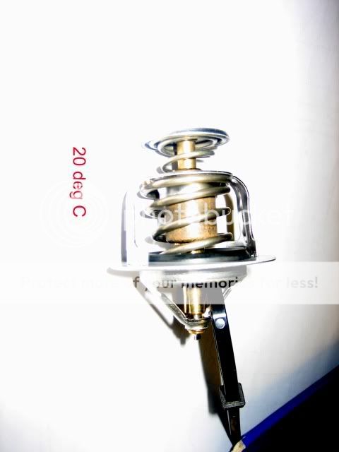
The wax in the stat is located in what can be described as a piston within a cylinder, the piston being the lower and FIXED to the pointed end of the cage.
The seal between piston and cylinder is in the pointed end of the stat and as such, is in the rad to stat pipe - ie the cooler side.
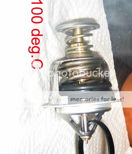
From trials, when the stat (Blueprint tested) experiences around 98 deg C, the piston/cylinder is at at the point of separation, ie stat failure. As the wax at this point is fluid, it can, (and I saw this in one extreme test I did) leak out between the piston/cylinder interface. The stat jammed in this position. However, when it cooled down a bit, and with a little persuation, the unit resumed its original shape.

Because wax has escaped, the remaining volume is smaller than the original. It is logical that this reduced volume will expand at a different rate to the full volume. ie slower to respond.
Is this the cause of a 'lazy stat', that folk keep mentioning? It certainly seems a viable explanation to me. Simple physics.

..............dirty ring on the center pin
and
..............bits of crap that circulating in the system and collecting in the edge,
Sounds logical
..............cone shaped pin and has a rubber seal type ring at the bottom,
and
..............mazda stat has the rubber ring around it to clean the pin as its opening and closing
Not sure. Very interesting bit this. Let you know my thoughts when I have dissected the Mazda stat
..............cone shaped pin stops the rubber going to far up the pin
Let you know my thoughts when I have dissected the Mazda stat. Taper in terface between 2 components? .......BUT......First thought was that it sounds like a perfect sealing arrangement to me.
Steve
User avatar
waycar8
Supreme Being
Posts: 3037
Joined: Fri Mar 17, 2006 9:35 pm
Location: west yorkshire

Re: coolant flow - (follow up to cooling diagram)

Post by waycar8 » Tue Mar 02, 2010 12:09 am

widdowson2008 wrote:
waycar8 wrote:..........
..............cone shaped pin stops the rubber going to far up the pin
Let you know my thoughts when I have dissected the Mazda stat. Taper in terface between 2 components? .......BUT......First thought was that it sounds like a perfect sealing arrangement to me.
From what I could gather the cone shaped pin or tapered pin doesnt come into contact with anything does it? as its located in the middle of the stat to either open or shut the base of the stat:? as you said a "piston" so wether its a cone shaped or just a pin type I would have thought the outcome would be the same unless theres something inside the cone shaped piston other than wax ect, but will hold that thought till you have disected the mazda stat ect :wink:
Image
User avatar
widdowson2008
Supreme Being
Posts: 1703
Joined: Tue Nov 18, 2008 10:15 pm
Location: N.E.Derbyshire

Re: coolant flow - (follow up to cooling diagram)

Post by widdowson2008 » Tue Mar 02, 2010 1:30 am

waycar8 wrote: From what I could gather the cone shaped pin or tapered pin doesnt come into contact with anything does it? as its located in the middle of the stat to either open or shut the base of the stat:? as you said a "piston" so wether its a cone shaped or just a pin type I would have thought the outcome would be the same unless theres something inside the cone shaped piston other than wax ect, but will hold that thought till you have disected the mazda stat ect :wink:
Image
Image
Bit hard to understand unless you have seen one opened up. The brass bits are the cylinder - not the piston.
Examine these 2 images, which are the Blueprint stat. No rubber bit and no taper, but in other respects, the same as a Mazda stat.

On both pics, you can see the brassy coloured bits - those parts are effectively all one piece which is the cylinder.
The smaller diameter, shiny steel bit, just visible, is the piston which is static - fixed to the cage.

If you now look at the 100 deg pic, you will see the stat lifted, exposing the static piston.

I expect the Mazda stat to be similar, with the exception that black seal, which the Blueprint doesn't have, will behave as a seal between the shiny piston and the brass cylinder. That's what I'm expecting, but as on so many previous occasions, the Mazda stat may have yet another little secret to share - once I have opened it up. :twisted: :twisted: :twisted:
Steve
User avatar
widdowson2008
Supreme Being
Posts: 1703
Joined: Tue Nov 18, 2008 10:15 pm
Location: N.E.Derbyshire

Re: coolant flow - (follow up to cooling diagram)

Post by widdowson2008 » Fri Mar 19, 2010 10:50 am

Have now got a brand new Mazda stat for testing. Hopefully, I'll be able to establish what the tapered part and the rubber 'thingy' is for without destroying the stat. (That's the plan anyway)

Re: The cooling system fact sheet I am producing.
I am producing it in a fashion which will be aimed at all levels, from a basic description up to a more in-depth technical level. ie-choose the level you are comfortable with. This is what's taking the time as there are many factors affecting the operation of the system.

There is one area I still can't get my head round and that is the bleeding procedure.
What I can't understand is why it is necessary to get the bottom hose hot. What does this PHYSICALLY do/prove. (apart from the obvious - getting the engine VERY hot)

It is widely stated that to bleed the system fully, the bottom hose needs to be hot, but no one has actually said why.
I know there are folk who successfully bleed their Bongos without over-revving, so I would like to hear from the pro-revving side.
Steve
munroman
Tribal Elder
Posts: 687
Joined: Tue Apr 01, 2008 6:00 pm
Location: Glasgow

Re: coolant flow - (follow up to cooling diagram)

Post by munroman » Fri Mar 19, 2010 11:46 am

Would the reason for having everything hot so that the system pressure is high, ditto with the revving, therefore there is more pressure and therefore flow through the bleed hose, making it more likely that air pockets will be dislodged by the flow and end up being bled from the highest point?
When asked about Western Civilisation, Ghandi said 'that would be a good idea'...
User avatar
widdowson2008
Supreme Being
Posts: 1703
Joined: Tue Nov 18, 2008 10:15 pm
Location: N.E.Derbyshire

Re: coolant flow - (follow up to cooling diagram)

Post by widdowson2008 » Fri Mar 19, 2010 12:30 pm

munroman wrote:Would the reason for having everything hot so that the system pressure is high, ditto with the revving, therefore there is more pressure and therefore flow through the bleed hose, making it more likely that air pockets will be dislodged by the flow and end up being bled from the highest point?
Your reply reflects precisely why I asked the question. If you take a look through the vast majority of the bleeding posts :roll:, '2500rpm for so many minutes' and 'bottom hose hot' crop up time and again. But the question 'WHY?' still remains.
Steve
User avatar
g8dhe
Supreme Being
Posts: 10704
Joined: Sun Apr 13, 2008 10:06 pm
Location: Worthing, West Sussex.

Re: coolant flow - (follow up to cooling diagram)

Post by g8dhe » Fri Mar 19, 2010 1:20 pm

Can't air get trapped between the bottom of the radiator and the thermostat ?
Your diagram Image
shows that it rises upwards, if the thermostat hasn't got an air hole, or it gets blocked if it does have one, then air will be trapped until the Thermostat opens, hence needing to make sure it does open and a hot lower hose shows that it has and that air isn't trapped.
Geoff
2001 Aero V6, AFT, full side conversion.
User avatar
missfixit70
Supreme Being
Posts: 12431
Joined: Fri Jun 01, 2007 3:53 pm
Location: weymouth

Re: coolant flow - (follow up to cooling diagram)

Post by missfixit70 » Fri Mar 19, 2010 1:49 pm

Bottom hose has to get hot (as well as the other bleeding criteria, hot heaters, no air bubbles out the bleed hose etc) because if it just gets warm, all this does is prove the thermostat opens, it DOES NOT prove the thermostat opens fully & is capable of shutting off the bypass/recirc port in the top of the stat housing (forcing a much bigger flow through the rad) until the bottom hose gets hot. Until you reach this point there is a fairly small flow through the rad even with the stat open, as the engine bypass/recirc port is still open & the stat is only just open, this means that if the stat will not open beyond this point or seal off the recirc/bypass port, then even if the fans kick in, there isn't going to be enough coolant flowing through the rad for the fans/air flow to cool & therefore if load is continued to be put on the engine there is a serious danger of overheating as the rad cannot remove enough heat from the smaller amount of flow through the rad.
Basically by ensuring that the bottom hose gets HOT (should easily get it to 80 degrees+, too hot to hold onto for long), you are ensuring that the system works as it should & opening/closing all parts of the system under load conditions, ensuring that no airlocks remain.
This is why it is important to check that the top sealing face inside the stat is clean & flat & capable of sealing against the top disc of the stat & why it is probably a good idea to fit a genuine Mazda stat that does what is expected in the design criteria.
If you have a stat that doesn't quite open enough, or is a litle bit lazy, it means your engine is going to run hotter than it should.
If you only get the system warm, you may bleed it succesfully, but if there are any issues you may still have air trapped & you haven't proved that the system is working as it should.
If the bottom hose gets hot & the temp is not controlled by the rad & fans (kicking in when they should, heaters are hot, water pump is ok), then chances are your rad is blocked/sludged & not capable of removing the heat, this may not show up until it is under driving load.
That's my theory anyway :wink:

No "over-revving" necessary, just the 2500 rpm :wink: without the revving/load (spin round the block works) it'll struggle to get hot enough.
Last edited by missfixit70 on Fri Mar 19, 2010 2:17 pm, edited 1 time in total.
You can't polish a turd - but you can roll it in glitter.
User avatar
missfixit70
Supreme Being
Posts: 12431
Joined: Fri Jun 01, 2007 3:53 pm
Location: weymouth

Re: coolant flow - (follow up to cooling diagram)

Post by missfixit70 » Fri Mar 19, 2010 1:53 pm

munroman wrote:Would the reason for having everything hot so that the system pressure is high, ditto with the revving, therefore there is more pressure and therefore flow through the bleed hose, making it more likely that air pockets will be dislodged by the flow and end up being bled from the highest point?
Yup I reckon that makes sense, higher revs, higher pressure/flow rates.
You can't polish a turd - but you can roll it in glitter.
User avatar
missfixit70
Supreme Being
Posts: 12431
Joined: Fri Jun 01, 2007 3:53 pm
Location: weymouth

Re: coolant flow - (follow up to cooling diagram)

Post by missfixit70 » Fri Mar 19, 2010 1:55 pm

g8dhe wrote:Can't air get trapped between the bottom of the radiator and the thermostat ?
Your diagramshows that it rises upwards, if the thermostat hasn't got an air hole, or it gets blocked if it does have one, then air will be trapped until the Thermostat opens, hence needing to make sure it does open and a hot lower hose shows that it has and that air isn't trapped.
A warm bottom hose shows that the stat opens, doesn't have to be hot to prove stat opening, just warm, but proving stat opening is not enough, it ain't that simple :wink:
You can't polish a turd - but you can roll it in glitter.
User avatar
widdowson2008
Supreme Being
Posts: 1703
Joined: Tue Nov 18, 2008 10:15 pm
Location: N.E.Derbyshire

Re: coolant flow - (follow up to cooling diagram)

Post by widdowson2008 » Fri Mar 19, 2010 2:11 pm

g8dhe wrote:Can't air get trapped between the bottom of the radiator and the thermostat ?
Your diagram Image
shows that it rises upwards, if the thermostat hasn't got an air hole, or it gets blocked if it does have one, then air will be trapped until the Thermostat opens, hence needing to make sure it does open and a hot lower hose shows that it has and that air isn't trapped.
That's what I thought, and indeed, it was the very reason I produced that drawing, to show where air could get trapped.
....and then.........
I examined a thermostat very closely (in fact, took one apart). What I found was that not only was the 'jiggle pin' a very loose fit in the main flange, it is also in the direct line of fire from the heater return flow coolant (providing the stat has been correctly fitted). Jiggle pin shaft is 1mm diameter fitting into a 3mm hole - what in engineering terms is a 'piss fit'. I don't think a 3mm hole could be tolerated anywhere else on the pipework. Conclusion? - designed to leak.
As far as 'getting blocked' is concerned, of the 7 stats I have tested, all the jiggle pins were loose (as per a new stat)
When the engine is running, the pump creates a turbulent flow within the stat mixing chamber, which in turn gives the 'jiggle pin' a fair old buffering. Because I cannot physically see inside the housing during normal working conditions, I can only assume that any air trapped below the stat flange will take its easiest route, and that would be through the jiggle pin hole. I hate assumptions, but I honestly believe that this is the true function of the jiggle pin - a bleeding aid. I cannot think of any other possible purpose for it being there. Always open to ideas though. :wink:
Steve
User avatar
mikeonb4c
Supreme Being
Posts: 22877
Joined: Sun Nov 05, 2006 10:49 pm
Location: Living with Mango Bongo in the North West but with a tendency to roam
Contact:

Re: coolant flow - (follow up to cooling diagram)

Post by mikeonb4c » Fri Mar 19, 2010 2:37 pm

missfixit70 wrote:
g8dhe wrote:Can't air get trapped between the bottom of the radiator and the thermostat ?
Your diagramshows that it rises upwards, if the thermostat hasn't got an air hole, or it gets blocked if it does have one, then air will be trapped until the Thermostat opens, hence needing to make sure it does open and a hot lower hose shows that it has and that air isn't trapped.
A warm bottom hose shows that the stat opens, doesn't have to be hot to prove stat opening, just warm, but proving stat opening is not enough, it ain't that simple :wink:
Just some thoughts, which I'm happy to have challenged:

I'm still curious why the workshop manual doesn't stress checking for a hot hose, if it is so essential. The only clue seems to be that it does (from memory) call for several minutes more running after the hose has showed signs of being warm, the implication being it wants the Bongo up to normal operating temperature. I'm not certain what a hot hose per se provides certain confirmation of (it might for example happen because poor circulation is preventing the rad. from cooling well so water is still hot when exiting it - fans coming on might be an indicator of this?). Conversely, a warm hose could tell you that circulation is good, because circulation and radiator cooling are working well and cooling the return flow well (bottom hoses have been reported by owners of healthy Bongos as being cool after a run).

What I suspect IS important is that there is a good flow rate around the system, however it is achieved. A healthy water pump, and unobstructed flow would clearly be key factors here. This 'dynamic' pressure will be important in purging the system of any air pockets. What I don't know is what you could use in order to confirm that healthy flow is taking place.

One other thought. I'm sure I gathered that it was the rear heater circuit that made Bongo bleeding the issue it is. Did I read on here that Ford Ranger heads don't have a bleed pipe attachment point because the Ranger doesn't have a rear heater? If that is true, then it might suggest the issue is really about getting air pockets out of the rear heater circuit. Once out of that circuit, bubbles ought to move round the system until they reach the highest point i.e. the header tank, resulting in a drop in header tank level as the void the bubble used to occupy is replaced by coolant. But the implication of the Ranger not having a bleed pipe should be that there is no danger (in a system with healthy dynamic pressure at least) of them lodging anywhere nasty, like in the ducting that cools the head.
User avatar
missfixit70
Supreme Being
Posts: 12431
Joined: Fri Jun 01, 2007 3:53 pm
Location: weymouth

Re: coolant flow - (follow up to cooling diagram)

Post by missfixit70 » Fri Mar 19, 2010 2:45 pm

Comparisons with the Ranger not having a rear heater are a bit of a non starter - it also isn't mid engined either with all the associated runs of pipwork, so that logic is a bit flawed IMO. removing the rear heater should hopefully simplify bleeding a bit though [-o<
You can't polish a turd - but you can roll it in glitter.
User avatar
Northern Bongolow
Supreme Being
Posts: 7722
Joined: Mon Mar 15, 2010 11:33 pm
Location: AKA Vanessa

Re: coolant flow - (follow up to cooling diagram)

Post by Northern Bongolow » Fri Mar 19, 2010 3:05 pm

hi all
kirsty in my opinion you have it spot on with the above statement,you increase revs gradually throughout the bleed proccess alongside the pressure rise to expell any residual air pockets.
one issue i have with the above is you CAN get air trapped in the bottom hose before the stat,i had one bleed when the weak bottom hose was sucked to half its diameter,
conclusion imho is that the jiggle pin is actually a float and only opperates properly when in contact with water ??????

ady
User avatar
mikeonb4c
Supreme Being
Posts: 22877
Joined: Sun Nov 05, 2006 10:49 pm
Location: Living with Mango Bongo in the North West but with a tendency to roam
Contact:

Re: coolant flow - (follow up to cooling diagram)

Post by mikeonb4c » Fri Mar 19, 2010 3:16 pm

OK, we'll leave the Ranger stuff out of this as being hard to verify. Any thoughts though on whether a hot bottom hose might be indicating poor cooling instead of good circulation?
Locked

Return to “Techie Stuff”