


Cooling system diagram
Moderators: Doone, westonwarrior
-
The Great Pretender

- Supreme Being
- Posts: 2671
- Joined: Thu Oct 19, 2006 10:10 pm
- Location: Wigan
Re: Cooling system diagram
Like a lower temp wax stat closing the bypass before the radiator begins to full flow Widdowson?..........is this what you are thinking?
To infinity and beyond
-
widdowson2008

- Supreme Being
- Posts: 1703
- Joined: Tue Nov 18, 2008 10:15 pm
- Location: N.E.Derbyshire
Re: Cooling system diagram
Aint got a clueThe Great Pretender wrote:Like a lower temp wax stat closing the bypass before the radiator begins to full flow Widdowson?..........is this what you are thinking?
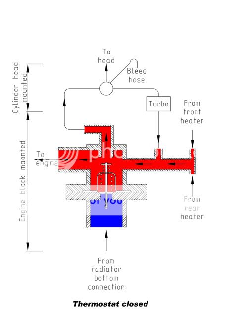
Looking at some pics I have got from the Doone establishment, one, of the thermostat housing, shows a view looking directly into the flange that the return flow from the rad pipework is bolted to. Never seen inside one but there is what appears to be a seating that the thermostat sits on when its fully closed.
However, if you have a closer look, the stat seating area has a simicircular notch cut out on the engine side of it. What the hell is that for? It has a purpose. I could waffle on with all sorts of crap and have fantasys all night long. Until I physically look inside, ideally on one thats been split on the centre, then the internal porting remains one of lifes mysteries. ........or at least until someone gets an angle grinder and ..........
Steve
-
missfixit70

- Supreme Being
- Posts: 12431
- Joined: Fri Jun 01, 2007 3:53 pm
- Location: weymouth
Re: Cooling system diagram
From testing mine (old & new) in a pan of water & watching their operation, it is just a basic stat, as the stat opens, flow is allowed into the bottom of the housing, the top plate moves up & from looking at the photos provided by Allan, it will seat on the top face inside the housing, closing off the bypass, maybe only partially? I guess someone'd need to do a pan of water test with a new stat in the housing to see if this is actually the case?
Last edited by missfixit70 on Sun Nov 15, 2009 1:37 am, edited 1 time in total.
You can't polish a turd - but you can roll it in glitter.
-
missfixit70
- Supreme Being
- Posts: 12431
- Joined: Fri Jun 01, 2007 3:53 pm
- Location: weymouth
Re: Cooling system diagram
Do you mean this one Steve? (From Allans Vehicle Services website).

If so this is the top end of the thermostat housing, the cut out area is just from the casting/machining of the hole through to the flange that mounts onto the engine. the bit that looks like a seat is the bypass exit where the top plate of the stat seats or restricts flow when it is open at the bottom to allow flow in from the bottom hose from the rad. Back to this diagram
I think you are possibly looking for complications where there aren't any & getting confused between the thermostat & it's housing, study the thermostat housing pics, no need to cut one open
If so this is the top end of the thermostat housing, the cut out area is just from the casting/machining of the hole through to the flange that mounts onto the engine. the bit that looks like a seat is the bypass exit where the top plate of the stat seats or restricts flow when it is open at the bottom to allow flow in from the bottom hose from the rad. Back to this diagram
mikexgough wrote:this might help.......to show how a thermostat opens at different temperatures - IMHO and I'm prepared to be shot at dawn....... the only real effective bleed is at the 98c setting......BUT how many owners bleed the system at that point........ you have to wonder that of you bleed when the thermostat just opens.....do you in effect clear all of the air from the system.......
I'll book the wall now....... and bring my own blindfold.......
I think you are possibly looking for complications where there aren't any & getting confused between the thermostat & it's housing, study the thermostat housing pics, no need to cut one open
You can't polish a turd - but you can roll it in glitter.
-
widdowson2008
- Supreme Being
- Posts: 1703
- Joined: Tue Nov 18, 2008 10:15 pm
- Location: N.E.Derbyshire
Re: Cooling system diagram
Thats the onemissfixit70 wrote:Do you mean this one Steve? (From Allans Vehicle Services website).
If so this is the top end of the thermostat housing, the cut out area is just from the casting/machining of the hole through to the flange that mounts onto the engine. the bit that looks like a seat is the bypass exit where the top of the stat seats or restricts flow. I think you are possibly looking for complications where there aren't any & getting confused between the thermostat & it's housing, study the thermostat housing pics, no need to cut one open
Youre right - forgot about the machi.......hold on?.....not sure about that Kirsty - dont think the half round is owt to do with the casting/machining .. hole through to the flange that mounts onto the engine - not on same centre line......or is it?? maybe the slight angle the pics being taken from.
Yup, - think thats it.
STOP steve - Kirsty is right.
Sorry about that - senior moment.
and you are so right. Dont need to go looking for complications
You know its great when you get to my age - the phrase 'senior moment' gets you out of all sorts of tight places.
Steve
-
widdowson2008
- Supreme Being
- Posts: 1703
- Joined: Tue Nov 18, 2008 10:15 pm
- Location: N.E.Derbyshire
Re: Cooling system diagram
For public scrutiny - all part of understanding
1 - are these diagrams correct?
2 - do you understand them.


1 - are these diagrams correct?
2 - do you understand them.
Steve
-
missfixit70
- Supreme Being
- Posts: 12431
- Joined: Fri Jun 01, 2007 3:53 pm
- Location: weymouth
Re: Cooling system diagram
In my opinion the flow goes into the top of the stat from the bypass/recirc pipe, if you look at yours, you seem to have got very confused with which way it goes, the first one is going up & out & the second one has somehow turned around.
If the main flow is going into the block from the side of the stat housing, IMO, it must come back around the engine via the head & back into the top of the stat, or it just doesn't & can't make sense. I don't think it suddenly changes direction for no reason?
The flow back into the top of the stat from the bypass/recirc pipe will be cooled to some degree on the first one, otherwise if it's as shown, the stat would be open as it's shown as hot.
The flow returning from the heaters (acting as rads to dissipate heat along with the long runs of pipework) & expansion tank( may be worth adding this label on the diagram) should have been cooled to some degree on the first diagram, on the second one the degree of cooling from this circuit should be dependant on how much the heaters are being used?
Still not sure on turbo flow direction I think would make more sense from a cooling point of view if it were going up from the heater return pipe to the 4 way connection on the head, rather than the coolant heated by the engine then going on to the turbo, but then the turbo should be happier running at slightly higher temps being on the exhaust outlet?
Until I get a chance to measure temperatures properly from cold to help determine more accurately whether these educated deductions are true, I can't say for sure?
It may be an idea to use temperature ranges(approx) for the colours?
I know it sounds like constant criticism, but you did ask for me to be honest Steve good work on the drawings 
What do the rest of you think?
If the main flow is going into the block from the side of the stat housing, IMO, it must come back around the engine via the head & back into the top of the stat, or it just doesn't & can't make sense. I don't think it suddenly changes direction for no reason?
The flow back into the top of the stat from the bypass/recirc pipe will be cooled to some degree on the first one, otherwise if it's as shown, the stat would be open as it's shown as hot.
The flow returning from the heaters (acting as rads to dissipate heat along with the long runs of pipework) & expansion tank( may be worth adding this label on the diagram) should have been cooled to some degree on the first diagram, on the second one the degree of cooling from this circuit should be dependant on how much the heaters are being used?
Still not sure on turbo flow direction
Until I get a chance to measure temperatures properly from cold to help determine more accurately whether these educated deductions are true, I can't say for sure?
It may be an idea to use temperature ranges(approx) for the colours?
I know it sounds like constant criticism, but you did ask for me to be honest Steve
What do the rest of you think?
Last edited by missfixit70 on Mon Nov 16, 2009 1:21 am, edited 1 time in total.
You can't polish a turd - but you can roll it in glitter.
-
widdowson2008
- Supreme Being
- Posts: 1703
- Joined: Tue Nov 18, 2008 10:15 pm
- Location: N.E.Derbyshire
Re: Cooling system diagram
What I am trying to acieve with the thermostat housing drawing is an understanding of what it is like inside - the porting. Compare the two diagrams
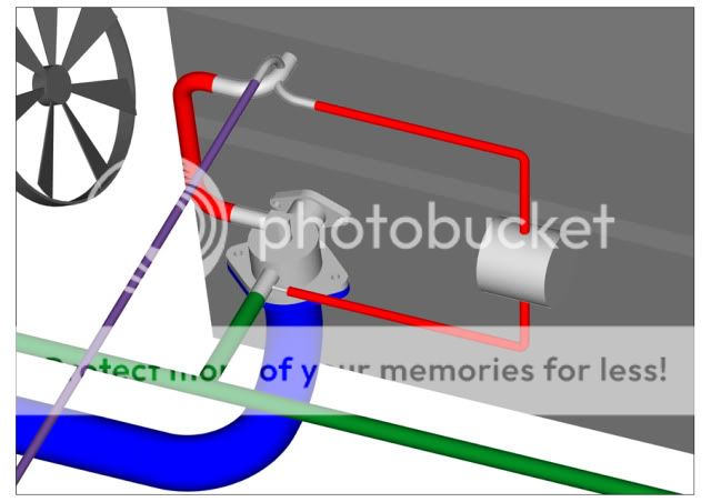
(on the 3D drawing) Ihe green pipes coming from the front/rear heaters are 'T'd', with the outgoing branch going into the top of thermostat housing.
Between the T and the housing is another connection (smaller red pipe) from the turbo.
This matches with the Thermostat drawing.
The elbow at the top (which is part of the housing casting) goes into the 4 way elbow that goes into the cylinde head (the larger red pipe).
Also involved in the 4 way elobow are 2 more pipes, the purple one is the bleed pipe, and the other small red on is to the other side of the turbo.
Can you see why it was so important to get the original circuit correct?
another thing - in the absence of verified information, it was the best I could do - I produced the thermostat section from Allens pics. Without phsically splitting a stat housing with an angle grinder to see exactly what its like inside, I just don't know.
Flow direction? I need verification from someone. Again, I just don't know.
The whole object of this excercise is to get abswers to all these 'I just don't knows'
Steve
-
missfixit70
- Supreme Being
- Posts: 12431
- Joined: Fri Jun 01, 2007 3:53 pm
- Location: weymouth
Re: Cooling system diagram
In terms of the porting & piping, that's spot on IMO Steve  matches up with the 3d as you say & illustrates the internals nice & clearly relative to the physical components.
The rest is just nitpicking on the options for flow directions/temperature conditions
The rest is just nitpicking on the options for flow directions/temperature conditions
You can't polish a turd - but you can roll it in glitter.
-
mikexgough

- Supreme Being
- Posts: 6158
- Joined: Mon Sep 08, 2008 9:02 pm
- Location: Cambridgeshire - where the all the Slodgers reside
- Contact:
Re: Cooling system diagram
looks good to me......will have the engine covers up later just to be sure that what the head says is right........is right...
Well done Steve......on your hard work...... Now who is going to to produce the "Dummies Guide Script".....
Well done Steve......on your hard work...... Now who is going to to produce the "Dummies Guide Script".....
Conversant with Bongo Top Pinion Oil Seals
Bongo owning Velotech Cycle Mechanic
Bongo owning Velotech Cycle Mechanic
-
widdowson2008
- Supreme Being
- Posts: 1703
- Joined: Tue Nov 18, 2008 10:15 pm
- Location: N.E.Derbyshire
Re: Cooling system diagram
Sent you a pmmikexgough wrote:looks good to me......will have the engine covers up later just to be sure that what the head says is right........is right...
Well done Steve......on your hard work...... Now who is going to to produce the "Dummies Guide Script".....
Steve
-
dandywarhol

- Supreme Being
- Posts: 5446
- Joined: Mon Dec 19, 2005 10:18 pm
- Location: Edinburgh
Re: Cooling system diagram
Looking at it again I think the turbo coolant wil flow from the 'stat to the head - from hot to hotter and then travel through the head to the far side and continue to the radiator
Whale oil beef hooked
Renault Lunar Telstar
Yamaha TD1C 250, Merc SLK200, KTM Duke 690
Renault Lunar Telstar
Yamaha TD1C 250, Merc SLK200, KTM Duke 690
-
missfixit70
- Supreme Being
- Posts: 12431
- Joined: Fri Jun 01, 2007 3:53 pm
- Location: weymouth
Re: Cooling system diagram
That's kind of where my thoughts were going, but I'd want to try & show that with some measurements, even if it's just comparative by touch as it warms up from cold.dandywarhol wrote:Looking at it again I think the turbo coolant wil flow from the 'stat to the head - from hot to hotter and then travel through the head to the far side and continue to the radiator
You can't polish a turd - but you can roll it in glitter.
-
widdowson2008
- Supreme Being
- Posts: 1703
- Joined: Tue Nov 18, 2008 10:15 pm
- Location: N.E.Derbyshire
Re: Cooling system diagram
Are you guys talking about the direction arrow on the 'thermostat midway' diagram?missfixit70 wrote:That's kind of where my thoughts were going, but I'd want to try & show that with some measurements, even if it's just comparative by touch as it warms up from cold.dandywarhol wrote:Looking at it again I think the turbo coolant wil flow from the 'stat to the head - from hot to hotter and then travel through the head to the far side and continue to the radiator
If so, then I would agree - my fault, draughting error. the arrow should be pointing upward.
Sorry
Steve
-
missfixit70
- Supreme Being
- Posts: 12431
- Joined: Fri Jun 01, 2007 3:53 pm
- Location: weymouth
Re: Cooling system diagram
That as well (although I believe that is actually the right way & the flow is actually downwards as I said before) , but we're talking about the flow through the turbo, which you show as going downwards into the line that returns from the heaters to the side of the stat, but uless someone has some measurements to back it up it's hypothesis for now.
You can't polish a turd - but you can roll it in glitter.