


Looking on lushprojects - http://www.lushprojects.com/bongopartsm ... mgno=.html - I'd say pointy end down, disc end up.
If it was disc end down, the disc is doing nothing that the thermostat itself isn't already doing, I think?
Cooling system diagram
Moderators: Doone, westonwarrior
-
missfixit70

- Supreme Being
- Posts: 12431
- Joined: Fri Jun 01, 2007 3:53 pm
- Location: weymouth
Re: Cooling system diagram
You can't polish a turd - but you can roll it in glitter.
-
dandywarhol

- Supreme Being
- Posts: 5446
- Joined: Mon Dec 19, 2005 10:18 pm
- Location: Edinburgh
Re: Cooling system diagram
Agreed Kirsty but I really want to know for definite............ 
Last edited by dandywarhol on Fri Nov 06, 2009 9:11 pm, edited 1 time in total.
Whale oil beef hooked
Renault Lunar Telstar
Yamaha TD1C 250, Merc SLK200, KTM Duke 690
Renault Lunar Telstar
Yamaha TD1C 250, Merc SLK200, KTM Duke 690
-
haydn callow

- Supreme Being
- Posts: 5778
- Joined: Mon Jan 08, 2007 9:50 pm
- Location: Somerset
- Contact:
Re: Cooling system diagram
Where's Allan when you need him ???......give him a dig Doone !!! Thanks
-
widdowson2008

- Supreme Being
- Posts: 1703
- Joined: Tue Nov 18, 2008 10:15 pm
- Location: N.E.Derbyshire
Re: Cooling system diagram
If the diagram in Kirstys post is correct, then the pointed end is DEFINITELY pointing downward, with the end showing the spring uppermost.dandywarhol wrote:Agreed Kirsty but I really want to know for definite............
The photo in Dandys post showing the thermostat (courtesy of Bongobits) is basically upside down.
The only way it can be the other way up is for the Japs to have got the diagram wrong.
Pointed it out several posts ago - it was overlooked.
Steve
-
mikexgough

- Supreme Being
- Posts: 6158
- Joined: Mon Sep 08, 2008 9:02 pm
- Location: Cambridgeshire - where the all the Slodgers reside
- Contact:
Re: Cooling system diagram
Which makes sense as the temperature sensing "bulb" of the Thermometer is between the spring in the "pointy" end......therefore in the coolant flow return from the radiator......so it can start to open at the predetermined temperature and pressure...widdowson2008 wrote:If the diagram in Kirstys post is correct, then the pointed end is DEFINITELY pointing downward, with the end showing the spring uppermost.dandywarhol wrote:Agreed Kirsty but I really want to know for definite............
The photo in Dandys post showing the thermostat (courtesy of Bongobits) is basically upside down.
The only way it can be the other way up is for the Japs to have got the diagram wrong.
Pointed it out several posts ago - it was overlooked.
Conversant with Bongo Top Pinion Oil Seals
Bongo owning Velotech Cycle Mechanic
Bongo owning Velotech Cycle Mechanic
-
haydn callow
- Supreme Being
- Posts: 5778
- Joined: Mon Jan 08, 2007 9:50 pm
- Location: Somerset
- Contact:
Re: Cooling system diagram
Woooop's gonna think again...photo's to follow
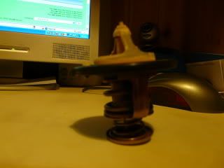 that's my stat removed last week...It fell out and I don't remember which way round it was for sure....the new one would only go one way.
However...I think it goes the way it is in the photo.....co's...there is a white limescale deposit all over the top surface and the bottom below the seal is clean brass.....that is what I would expect if it sits as in the photo
that's my stat removed last week...It fell out and I don't remember which way round it was for sure....the new one would only go one way.However...I think it goes the way it is in the photo.....co's...there is a white limescale deposit all over the top surface and the bottom below the seal is clean brass.....that is what I would expect if it sits as in the photo
Last edited by haydn callow on Fri Nov 06, 2009 10:59 pm, edited 1 time in total.

Re: Cooling system diagram
Can anybody postively confirm the pointy end of the thermostat points down into the thermostat cover?
He's home now.Where's Allan when you need him ???......give him a dig Doone !!! Thanks
The disc end goes up into the thermostat housing.
There's a 'lump' on the rubber seal of the thermostat and this points towards the drivers door.
Haydn, that must mean that it's upside down in your photo, as you have stood it on its flatter end.
Please note that Allan has not read through these posts and has not looked at the diagrams, so can't comment on them.
Allans Garage retired. Try PGS (Plymouth Garage Services) or Mayflower Auto Services Plymouth
-
The Great Pretender

- Supreme Being
- Posts: 2671
- Joined: Thu Oct 19, 2006 10:10 pm
- Location: Wigan
Re: Cooling system diagram
Locked threads widdowson................. Must have been caused by me............ 
One of my first threads posted here was if the stat is an 82c one what temp does it open at? (As this is the temp the head should be held at. (It runs at 85c, modulating between 80 to 90c with the stat on the OUTLET of the head) So what temp would the head need to be at to return coolant above 82c?)
Answer 2 bloody hot.
If you want to find out what happens on the bottom hose put a temp sensor at each end. That will supprise you, you then need to find out how the internal flow affects the system.
To infinity and beyond
-
widdowson2008
- Supreme Being
- Posts: 1703
- Joined: Tue Nov 18, 2008 10:15 pm
- Location: N.E.Derbyshire
Re: Cooling system diagram
So the Japs did get it right in their diagram after all.Haydn, that must mean that it's upside down in your photo, as you have stood it on its flatter end.
Steve
-
mikexgough
- Supreme Being
- Posts: 6158
- Joined: Mon Sep 08, 2008 9:02 pm
- Location: Cambridgeshire - where the all the Slodgers reside
- Contact:
Re: Cooling system diagram
This article might help folks have an understanding of a thermostat on the return side of a cooling system...... it is for a Lotus Elise using a K-series engine (which were notorious for Head gasket failure) however, ignore the K series solution to prevent HGF and just focus on the theory of how such a system works and the progressive opening of the thermostat http://web.tiscali.it/elise_s1/index.htm
Last edited by mikexgough on Sat Nov 07, 2009 11:12 am, edited 1 time in total.
Conversant with Bongo Top Pinion Oil Seals
Bongo owning Velotech Cycle Mechanic
Bongo owning Velotech Cycle Mechanic
-
widdowson2008
- Supreme Being
- Posts: 1703
- Joined: Tue Nov 18, 2008 10:15 pm
- Location: N.E.Derbyshire
Re: Cooling system diagram
I read through that post (marathon jobThe Great Pretender wrote:Locked threads widdowson................. Must have been caused by me............
One thing it did highlight, and this one is showing similar signs, is that no one really is 100% sure how the system works in the finer detail. But I think it is only the finer detail where folk are disagreeing.
Going back to object of the excercise, from my perspective, all I am trying to get out of this is an accurate diagram which I can print out, take to the van, and and check things out.
Steve
-
mikexgough
- Supreme Being
- Posts: 6158
- Joined: Mon Sep 08, 2008 9:02 pm
- Location: Cambridgeshire - where the all the Slodgers reside
- Contact:
Re: Cooling system diagram
this might help.......to show how a thermostat opens at different temperatures - IMHO and I'm prepared to be shot at dawn....... the only real effective bleed is at the 98c setting......BUT how many owners bleed the system at that point........ you have to wonder that of you bleed when the thermostat just opens.....do you in effect clear all of the air from the system.......
I'll book the wall now....... and bring my own blindfold.......
I'll book the wall now....... and bring my own blindfold.......
Conversant with Bongo Top Pinion Oil Seals
Bongo owning Velotech Cycle Mechanic
Bongo owning Velotech Cycle Mechanic
-
widdowson2008
- Supreme Being
- Posts: 1703
- Joined: Tue Nov 18, 2008 10:15 pm
- Location: N.E.Derbyshire
Re: Cooling system diagram
Just read through your link. I think I can actually see light at the end of this tunnel. (thermostat/bypass wise at least)mikexgough wrote:This article might help folks have an understanding of a thermostat on the return side of a cooling system...... it is for a Lotus Elise using a K-series engine (which were notorious for Head gasket failure) however, ignore the K series solution to prevent HGF and just focus on the theory of how such a system works and the progressive opening of the thermostat http://web.tiscali.it/elise_s1/index.htm
With the exception of the expansion tank involvement, this (to me) looks a very similar circuit to the Bongo one in my (limited) understanding.
.......and just seen your very latest re:thermostat. This thinking makes sense.
Move over and make space at the wall (I will not need the blindfold cos I'm in the dark anyway - but learning all the time)
Steve
-
miker
Re: Cooling system diagram
To answer a point that seems to be made quite often on this forum and was made early on in this thread, and happy to join the queue at the wall if I'm wrong, but the comment about bottom hose of the rad being cool while top is hot - surely this means the rad is doing its job.ie. cooling the fluid passing through it. That of course assumes the coolant flows from top of rad to bottom.
-
mikexgough
- Supreme Being
- Posts: 6158
- Joined: Mon Sep 08, 2008 9:02 pm
- Location: Cambridgeshire - where the all the Slodgers reside
- Contact:
Re: Cooling system diagram
miker wrote:To answer a point that seems to be made quite often on this forum and was made early on in this thread, and happy to join the queue at the wall if I'm wrong, but the comment about bottom hose of the rad being cool while top is hot - surely this means the rad is doing its job.ie. cooling the fluid passing through it. That of course assumes the coolant flows from top of rad to bottom.
Conversant with Bongo Top Pinion Oil Seals
Bongo owning Velotech Cycle Mechanic
Bongo owning Velotech Cycle Mechanic