


a radiator has a TOP..& .Bottom....connected together by a load of tubes/fins
The top bit is the top tank
The bottom is the bottom tank.
It has always been thus.
when you tthe rad cap off you can see a void.....= top tank
Cooling system diagram
Moderators: Doone, westonwarrior
-
haydn callow

- Supreme Being
- Posts: 5778
- Joined: Mon Jan 08, 2007 9:50 pm
- Location: Somerset
- Contact:
-
widdowson2008

- Supreme Being
- Posts: 1703
- Joined: Tue Nov 18, 2008 10:15 pm
- Location: N.E.Derbyshire
Re: Cooling system diagram
haydn callow wrote:I know this has been debated to death in the past. But I am changing my thoughts on the whole subject..
I assume your cooling system is in "tip top" condition...
You are getting very hot coolant coming out of the engine via the top hose and then moving down through the rad and also being cooled as it does so, the stat is open co's the engine is hot so the cooled coolant passes along the bottom hose and through the stat to be reheated in the Head.
I used to think the bottom hose was cool co's the stat was closed...Now after more thought and watching my gauges fluctuate around the 85/90C temp range I belive the stat is opening/closing all the time and the radiator in good condition is doing it's job very well.
That is exactly 100% what I am thinking.
My bottom hose doesn't get very warm at all, even after a run of 200 miles, and I thought it may be that the bottom end of radiator is clogged up. (but I very much hope not)
Then I nurtured the thought that perhaps the radiator is indeed very good at its job.
AND
if you put this thinking together with what Dandy has just produced, then..................fascinating stuff - I can see I'm not going to get much sleep tonight - this needs thinking through........and wads of paper/pencils.
This really warants a cooling system diagram - will do one, get it perused by you guys, and then post (if anyone is interested)
Thank you gentlemen for getting me a little further along the road of understanding.
Last edited by widdowson2008 on Thu Nov 05, 2009 9:47 pm, edited 2 times in total.
Steve
-
dandywarhol

- Supreme Being
- Posts: 5446
- Joined: Mon Dec 19, 2005 10:18 pm
- Location: Edinburgh
Re: Cooling system diagram
The latter..............widdowson2008 wrote:Excellent Dandy - The soup becomes a little clearer.
But this has thrown up another queryAre you saying that (in your opinion) the radiator has a top tank and by suggestion, a bottom tank?dandywarhol wrote:It's my understanding (and some will disagree) that only the radiator's top tank is ........
or is it that the radiator is zoned?
or perhaps,
the circuit from rad to expansion tank can cope with the engine cooling requirements under normal running conditions, and the lower half only needs to be brought into play when the engine is working extra hard?
to your query Haydn - on the bottom of the thermostat is a bypas valve - would it be possible thge 'stat isn't fully opening but it is allowing the bypass valve to operate and regulate/fluctuate the temperature?
I still don't think the bottom hose will get fully warm until there's a heat flow from the radiator bottom tank to the engine, via the 'stat, and that'll only happen when the 'stat is fully open.
Also, there's no water pump in the diagram......
Thanks to Bongobits for the pic

Whale oil beef hooked
Renault Lunar Telstar
Yamaha TD1C 250, Merc SLK200, KTM Duke 690
Renault Lunar Telstar
Yamaha TD1C 250, Merc SLK200, KTM Duke 690
-
haydn callow
- Supreme Being
- Posts: 5778
- Joined: Mon Jan 08, 2007 9:50 pm
- Location: Somerset
- Contact:
Re: Cooling system diagram
Dandy..when you say bypass valve on the bottom of the stat. do you mean what I call a "jiggle" pin.......yes I have on of those , but, I cannot see it allowing enough coolant flow to be of significance...I understand this is to allow air to escape.
-
mikexgough

- Supreme Being
- Posts: 6158
- Joined: Mon Sep 08, 2008 9:02 pm
- Location: Cambridgeshire - where the all the Slodgers reside
- Contact:
Re: Cooling system diagram
Now I can't comment regarding coolant bleeding as I got it right first time using my own method and I can't compare an old radiator bleed against a new radiator bleed (if this makes sense) as I only have bled a mine with a new radiator.dandywarhol wrote:It's my understanding (and some will disagree) that only the radiator's top tank is in use for the majority of the time. The coolant circulating around the various pipes and heater matrices is sufficient.
I would assume then that with a system flush through and after a replenish of coolant with a new radiator, any system would be as good as it gets for flow of coolant around the engines cooling system....
Therefore the way that is suggested as to how the circuit works, that Dandy describes that......in the main, the main and heater radiators work the hardest, then when the engine temperature is high enough through use, the Thermostat opens to circulate the cooled down coolant from the radiator around the remainder of the system, as for the open & shut of the thermostat, I am open to the theory of that model.
Shoot me down in flames here, but for me the only way the thermostat will open properly to allow the system circulate the coolant to allow the system to be bled properly is for both the heaters to be very hot, not just warm, (I did my system bleed in July when the ambient temperature was 24c so the engine got warm quite quickly)......and with this action the bottom hose then got warm which allowed me to thoroughly clear the system of air.
The reason I agree with Dandy's understanding of the coolant circuit ( I have looked at the Bongo parts diagrams) is that I cant see any valves that isolate the coolant from the heater matrices....for example on the A series engine as fitted to minis and other BMC vehicles they had such a valve fitted which isolated all or part of the heater circuit as part of the hot/cold selection for the heater thus eliminating complicated flaps and cables....
So in essence this reinforces my thoughts about the heater temperature being crucial when bleeding the system as the system has in effect 3 radiators which are cooling the engine.
Conversant with Bongo Top Pinion Oil Seals
Bongo owning Velotech Cycle Mechanic
Bongo owning Velotech Cycle Mechanic
-
missfixit70

- Supreme Being
- Posts: 12431
- Joined: Fri Jun 01, 2007 3:53 pm
- Location: weymouth
Re: Cooling system diagram
If you have the heaters on full blast while trying to bleed it - it will take much longer IMO as they are acting as a cooling rad for the coolant, you want it to heat up quickly when you're bleeding, not dissipate that heat via the heater matrixes (which have constant coolant flow - it's the airflow over them that is the heater control)
You can't polish a turd - but you can roll it in glitter.
-
dandywarhol
- Supreme Being
- Posts: 5446
- Joined: Mon Dec 19, 2005 10:18 pm
- Location: Edinburgh
Re: Cooling system diagram
Nope - the jiggle pin is the little ball valve in the upper part of the 'stat which allows trapped air past. The bypass valve is the plate at the bottom of the stat which (I can't speak for the Bongo as I haven't had to remove it) allows coolant to flow in the bypass system when the 'stat is closed.haydn callow wrote:Dandy..when you say bypass valve on the bottom of the stat. do you mean what I call a "jiggle" pin.......yes I have on of those , but, I cannot see it allowing enough coolant flow to be of significance...I understand this is to allow air to escape.
This threads starting to grow - I hope TGP is looking in..............
Whale oil beef hooked
Renault Lunar Telstar
Yamaha TD1C 250, Merc SLK200, KTM Duke 690
Renault Lunar Telstar
Yamaha TD1C 250, Merc SLK200, KTM Duke 690
-
haydn callow
- Supreme Being
- Posts: 5778
- Joined: Mon Jan 08, 2007 9:50 pm
- Location: Somerset
- Contact:
Re: Cooling system diagram
So what triggers this "bypass" valve into opening ?? Somthing is defo opening/closing in my system to make my gauges behave the way they do.
-
dandywarhol
- Supreme Being
- Posts: 5446
- Joined: Mon Dec 19, 2005 10:18 pm
- Location: Edinburgh
Re: Cooling system diagram
I haven't seen into a bongo cooling system in depth but with a bypass system thermostat the "disc" at the bottom of the 'stat allows coolant to flow through the bypass system during warmup and whenever the 'stat opens the disc (attached to the main thermostat valve) moves down and closes off the bypass system and allows the full flow of coolant through the maim thermostat valve. I know I've asked this question before but forgotten the answer, in the above photo of the thermostat, which end of it goes into item number 15-172, the thermostat cover? the pointy end or the disc valve end?http://www.lushprojects.com/bongoparts/ ... 2).html#10
Whale oil beef hooked
Renault Lunar Telstar
Yamaha TD1C 250, Merc SLK200, KTM Duke 690
Renault Lunar Telstar
Yamaha TD1C 250, Merc SLK200, KTM Duke 690
-
mikexgough
- Supreme Being
- Posts: 6158
- Joined: Mon Sep 08, 2008 9:02 pm
- Location: Cambridgeshire - where the all the Slodgers reside
- Contact:
Re: Cooling system diagram
Exactly....... so if the following is added to the bleed sequence - "select full hot on the heater controls (don't switch fans on at this point) then allow the engine to come to normal temperature, before checking the heat at the heaters by using the fan switches" - the 3 radiators will be allowed to get fully hot quicker plus the "bleeder" will have the mechanisms in place to enable a more stress free and positive bleed sequence experience.....missfixit70 wrote:If you have the heaters on full blast while trying to bleed it - it will take much longer IMO as they are acting as a cooling rad for the coolant, you want it to heat up quickly when you're bleeding, not dissipate that heat via the heater matrixes (which have constant coolant flow - it's the airflow over them that is the heater control)
Conversant with Bongo Top Pinion Oil Seals
Bongo owning Velotech Cycle Mechanic
Bongo owning Velotech Cycle Mechanic
-
widdowson2008
- Supreme Being
- Posts: 1703
- Joined: Tue Nov 18, 2008 10:15 pm
- Location: N.E.Derbyshire
Re: Cooling system diagram
From the diagram, it appears to be the pointed end goes into 15-172 and the spring end goes uppermost.dandywarhol wrote: in the above photo of the thermostat, which end of it goes into item number 15-172, the thermostat cover? the pointy end or the disc valve end?http://www.lushprojects.com/bongoparts/ ... 2).html#10
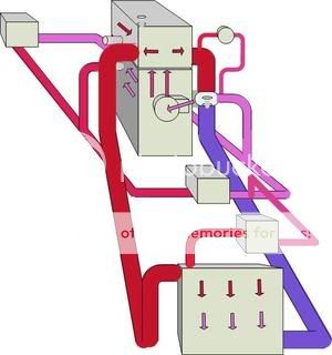
Incidentally, on my quest to find out how the cooling system works, and following a lead from one of Alans posts, I found this diagram (forget who did it, but whoever it was,
Is this diagram correct?
and/or
Was it ever followed through? It seems to have been abandoned when the handbags came out.
Whichever is the case, its a good starting point for me. (unless advised otherwise)
Seems a pity to let this diagram fade into obscuritiy
Steve
-
alphabetter

- Bongolier
- Posts: 214
- Joined: Wed Feb 08, 2006 10:51 pm
Re: Cooling system diagram
Looks the same as mine

so I would say it's right. His colours are probably more useful than my red/blue which is too simplistic.
so I would say it's right. His colours are probably more useful than my red/blue which is too simplistic.
-
mikexgough
- Supreme Being
- Posts: 6158
- Joined: Mon Sep 08, 2008 9:02 pm
- Location: Cambridgeshire - where the all the Slodgers reside
- Contact:
Re: Cooling system diagram
dandywarhol wrote:Nope - the jiggle pin is the little ball valve in the upper part of the 'stat which allows trapped air past. The bypass valve is the plate at the bottom of the stat which (I can't speak for the Bongo as I haven't had to remove it) allows coolant to flow in the bypass system when the 'stat is closed.haydn callow wrote:Dandy..when you say bypass valve on the bottom of the stat. do you mean what I call a "jiggle" pin.......yes I have on of those , but, I cannot see it allowing enough coolant flow to be of significance...I understand this is to allow air to escape.
This threads starting to grow - I hope TGP is looking in..............
I asked an engineer pal......... here is his e-mail response
The aneroid thermostat, consists of a control valve that is energised by a vapour filled metal bellows.
The valve remains closed until a predetermined temperature and cooling system pressure has been reached ,usually between 75-84c and then the thermostat begins to open in the current flow.
It then progressively opens further as the coolant temperature rises until it is fully open at between 90-95c in usual cases and then continues to control the flow of coolant in accordance with engine cooling needs.
Jiggle pins are merely there to assist the bleed process when systems are refilled and any loose pins are forced to seal closed under pressure.
Often these thermostats are used in cooling systems that have a bypass arrangement so that the water pump constantly is replenished and circulates coolant prior to the operation of the thermostat.
Conversant with Bongo Top Pinion Oil Seals
Bongo owning Velotech Cycle Mechanic
Bongo owning Velotech Cycle Mechanic
-
dandywarhol
- Supreme Being
- Posts: 5446
- Joined: Mon Dec 19, 2005 10:18 pm
- Location: Edinburgh
Re: Cooling system diagram
Can anybody postively confirm the pointy end of the thermostat points down into the thermostat cover?
Either I misread a post a long time ago or got some bum info but I was lead to believe the pointy end went upwards towards the head..............
If it is fitted downwards then I have a totally different thought on the cooling system operation and will expand on it when the position of the 'stat is confirmed.........................c'mon - who's fitted one?
Whale oil beef hooked
Renault Lunar Telstar
Yamaha TD1C 250, Merc SLK200, KTM Duke 690
Renault Lunar Telstar
Yamaha TD1C 250, Merc SLK200, KTM Duke 690
-
missfixit70
- Supreme Being
- Posts: 12431
- Joined: Fri Jun 01, 2007 3:53 pm
- Location: weymouth
Re: Cooling system diagram
Fitted one, but I'm bu**ered if I can remember which way it goes 
You can't polish a turd - but you can roll it in glitter.