Thought these photos may help him and anyone else trying to identify the correct wire to measure with a multimeter when diagnosing a fault.
For more detail of the process see here http://www.igmaynard.co.uk/bongo/forum/ ... hp?t=16544
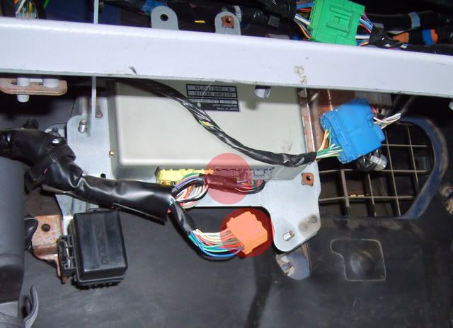
Black plastic ECU cover has been removed and the middle connector block of three (highlighted in red) is the one you're interested in. In this picture it's the one I've disconnected. The connector block is actually yellow.
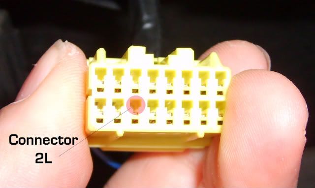
Hold the connector in the same orientation as in the pic below and count 3 from the bottom left to find pin 2L (highlighted in red). BTW 2L doesn't stand for 2 from left it's simply the numbering scheme used in the workshop manual. Now you know which pin to connect to turn the connector round and shove a wire with a bare end into the back of the pin you identified. Connect the other end of the wire to the positive of your meter and the negative of your meter to chassis.