Page 1 of 3
Alarm connections
Posted: Thu Jul 16, 2015 7:25 am
by sotal
I now have an alarm module to fit.
I've been through the wiring and am happy with where to pick up a lot of the wires but I have a few that I'm not sure about.
The following are just wires out of the unit - do they need fuses or diodes when connecting to the Bongo wiring and is there anywhere that is best to pick these wires up?
Door pin pos (Positive Door Input (+). Connect to the driver door pin switch circuit wire that shows +12v when the door is open.
Note: Consult owner manual for polarity.)
Door pin neg (Negative Door Input (-). Connect to the Driver door pin switch circuit wire that shows ground (-) when the door is open.
Note: Nearly all cars have negative door input. Consult owner manual for polarity.)
Interior Light (Negative Output (-). 250mA Interior Light. Connect to the wire that activates the vehicle’s interior light.)
Hazard Warning Light (Positive Hazard Light Output (+). Connect the wire to the circuit that shows +12v or only when the hazard lights are on. Left hazard light)
Hazard Warning Light (Positive Hazard Light Output (+). Connect the wire to the circuit that shows +12v or only when the hazard lights are on. Right hazard light)
Foot brake (Positive Input (+). Connect the blue/white wire that shows +12v when pressing the foot brake.)
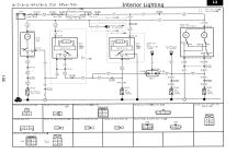
I couldn't understand why I would need two hazard warning light connections. Don't they all work together? The diagram shows a 7.5Amp fuse on those wires too.
Also do I just need to pick one of the door pin wires depending on the system used by the Bongo? If so which is it?
Does it need a connection to the interior light as well as the door pin? I thought that both of these would just be to activate the alarm from the same method (door opening)?
Re: Alarm connections
Posted: Thu Jul 16, 2015 9:58 am
by g8dhe
You need to use the "Door pin neg (Negative Door Input (-)" wire for the doors, it goes to ground when the doors are open.
The Interior Light is an OUTPUT - it turns the light on, its not detecting a door via that route.
You need both Side light connections so that it can workout that it is Hazard flashing and NOT direction flashing, i.e. both signals need to be present left and right at the same time.
If the diagram your using shows fuses then fit them, the fuses protect the wiring, the existing wiring will be rated differently and fused accordingly, the wires your adding will be a different gauge.
Re: Alarm connections
Posted: Thu Jul 16, 2015 10:02 am
by Simon Jones
I seem to recall the tailgate signal goes positive when opened rather than negative for the other 3 doors.
Re: Alarm connections
Posted: Thu Jul 16, 2015 1:45 pm
by g8dhe
They all appear the same, switch to Earth on opening .... left side is rear door, centre is sliding door and right hand side is cabin doors.
Re: Alarm connections
Posted: Thu Jul 16, 2015 7:30 pm
by sotal
Thanks for this,
With the door pin do I need to fit diodes or anything or can I just connect it up?
This bit confused me with the interior light:
The best places to find the door switch wire are:
• At the pin switch: when testing the pin switch, check wire to ensure that it ‘sees’ all the doors. Often, the passenger switch will cover all the doors even if the driver’s switch will not.
• At the interior light: this may not be your best choice if the vehicle has delayed interior light supervision, but it will work in many Hondas, or any vehicle with completely diode-isolated pin switches.
• Once you have determined the wire colour, the easiest place to connect to the wire is often at the kick panel, at the windscreen pillar, or in the running board. When an easy location is not available, running a wire to the interior light itself is often the best solution.
However you are correct that it says it is an output - do I really need that? Sounds like one I could just miss out?!
Re: Alarm connections
Posted: Thu Jul 16, 2015 8:09 pm
by jimmo62
Just been reading my notes from when I installed my alarm. I noted that I fed the negative door circuit connection on the alarm from both the side sliding door and the front doors. Since there are 2 separate feeds (one for the side door and one which is fed from both front doors) I used a diode on each feed to connect them both to the single alarm circuit. If you look at the diagram posted above you will see there is already a diode pack I3-06 which feeds the door open warning light on the dashboard. I connected my diodes in the same electrical polarity and tapped into the wires near the existing diode pack. This is located under the dash in the passenger footwell. The Red/Green is for the side door and the Red/White is for the 2 front doors.
Re: Alarm connections
Posted: Thu Jul 16, 2015 8:10 pm
by jimmo62
Not sure why it needs a connection to the foot brake - that seems a bit strange for an alarm!
Re: Alarm connections
Posted: Thu Jul 16, 2015 8:15 pm
by jimmo62
Sorry, one other point - my alarm had a separate boot alarm circuit which I connected to the rear tailgate switch by connecting to the Dark Green/Red wire in the rear tailgate light (the one which comes on when you open the tailgate). If you don't have a separate boot circuit on your alarm then just use another diode to connect it to the negative door input along with the front and side doors.
that way all the doors are now covered.
Re: Alarm connections
Posted: Thu Jul 16, 2015 8:15 pm
by sotal
jimmo62 wrote:Not sure why it needs a connection to the foot brake - that seems a bit strange for an alarm!
After the engine starts - it locks the doors 6 seconds after you press the brake pedal.
Just found the user manual says about the interior light - it is an output it puts the light on for 25 seconds after you unlock.
Re: Alarm connections
Posted: Thu Jul 16, 2015 8:17 pm
by sotal
jimmo62 wrote:Sorry, one other point - my alarm had a separate boot alarm circuit which I connected to the rear tailgate switch by connecting to the Dark Green/Red wire in the rear tailgate light (the one which comes on when you open the tailgate). If you don't have a separate boot circuit on your alarm then just use another diode to connect it to the negative door input along with the front and side doors.
that way all the doors are now covered.
I'm going to need some more wire at this rate. Half tempted to just use the shock sensor and ultrasonic sensors as they should go off if you open the door anyway!
Re: Alarm connections
Posted: Thu Jul 16, 2015 8:19 pm
by sotal
Re: Alarm connections
Posted: Thu Jul 16, 2015 8:22 pm
by sotal
Am I correct that it is Diagram C that I will need for the central locking? (In the installation manual above)
Re: Alarm connections
Posted: Thu Jul 16, 2015 8:43 pm
by jimmo62
Yes I think C is the one you need
Re: Alarm connections
Posted: Thu Jul 16, 2015 8:50 pm
by jimmo62
Looks like you have a boot circuit in the alarm so connect the rear door to that.
Re: Alarm connections
Posted: Thu Jul 16, 2015 9:28 pm
by sotal
jimmo62 wrote:Yes I think C is the one you need
Thanks
I think Job 1 will be to install the solenoid (when it arrives), then I will install power to the alarm module and install the ultrasonic sensors, the shock sensor and the siren. This will give me RCL and a basic alarm of sorts.
Job 2 will be to install the immobiliser circuit.
Job 3 will be to connect up the hazard lights to flash with the alarm.
I can then spend longer finding all the different connections and working out what I need for them!