Page 1 of 2
Electrical HRW (Rear defroster cfd page 96)
Posted: Tue Dec 09, 2014 6:40 pm
by hijimhere
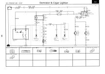
I have no heated rear window function - I have checked the 30 amp (under dash right hand lower pink one) thats ok. I decided to unplug the connector from the switch-the plug has 4 connections as does the switch. The switch illumination works. I suspect that we have somewhere, there being 4 connections, a relay which when powered uses the 30amp circuit to power the rear screen. I am a bit confused by cfd 96 - on the left it does seem to indicate a powered relay operation (feeding a resistance) which I took to be the HRW.
That was before I notice that the circuit was boxed with A/C on the top - does this mean "Air Conditioning"????
Flumoxed = I am having trouble trying to reconcile that a high load (30amp<) is being sent through a switch! Seems a bit of a no no sending such a current all the way to the back of the vehicle only controlled by 30amp fuse - a lot less than that is enough to start a fire.
So i have check continuity through the rear screen heater (it is a new screen), from the switch terminal to the rear screen and through the 30amp fuse board. This boxed and titled A/C circuit has a 30 amp and also a 10 amp showing on the cfd both going to a relay. Has anyone used cfd 96 to fix a heated rear screen problem? I have checked the listing of both fuse boards, the only listing is the 30 amp fuse - no other fuse or relay is listed as for HRW function!
Re: Electrical HRW (Rear defroster cfd page 96)
Posted: Wed Dec 10, 2014 11:36 am
by g8dhe
Yes its operated via the relay
Re: Electrical HRW (Rear defroster cfd page 96)
Posted: Wed Dec 10, 2014 12:19 pm
by TheStinkyHippy
Out of interest... how the heck do you get that from that diagram!
I see I1-07 and I1-06 with picture of cig socket..
Is I1-03 /I1-04 the rear demister?
What is I1-02?
I see link 84 is through to the instrument panel.. and 84 is the Rear Demister light on the dashboard?
Where is the button you push to make it come on?
Just trying to understand the diagrams.. one day I expect I will need to follow one

Re: Electrical HRW (Rear defroster cfd page 96)
Posted: Wed Dec 10, 2014 1:09 pm
by hijimhere
Thank you - boy am I glad I am not mad after all - it is the relay I am after - but I have now broken the switch. It would be nice to know which fuse the 10amp one is - replacement switch hunt for now.
Re: Electrical HRW (Rear defroster cfd page 96)
Posted: Wed Dec 10, 2014 11:55 pm
by g8dhe
Hover your mouse over the green fuse and a picture will pop up!
Or you could go to the start of the site (select which manual) and the tabs at the top will show you all about the fuses!
If your not into wiring diagrams the same applies, go to the top of the site and the fuse tabs will sort out a lot of problems for people.
Http://www.g8dhe.net/bwm
Re: Electrical HRW (Rear defroster cfd page 96)
Posted: Thu Dec 11, 2014 3:44 pm
by hijimhere
T1 - 2 is the switch for the HRW
T 1 - 1 is this mysterious relay (not showing on FB's)
Re: Electrical HRW (Rear defroster cfd page 96)
Posted: Thu Dec 11, 2014 4:20 pm
by g8dhe
The double headed arrows >> indicate connectors, rather than the device itself the connectors are sometimes someway away from from the device itself!
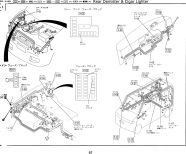
The locations of connectors and devices appears on the following page to the diagram - go Right once.
I1-02 - Is the switch connector. The switch is actually two (double) pole(s), one pole operates the LED light to indicate that the switch is operated, the other pole operates the relay itself. Switches are shown by the sloping line between two open/filled dots.
I1-01 - Is the relay and its connectors located under the bonnet on the offside wheel arch.
I1-03/4 - are the connectors to the actual heater strip, whilst I1-05 X-32,X-29 & X-09 are connectors in the loom as it runs back to the front of the vehicle.
Help on navigating the pages in the manuals is available
Help-
also on the
Colour Codes-
A useful table of electrical symbols is here
http://www.rapidtables.com/electric/ele ... ymbols.htm but be warned there are lots of variations actually in use!
Re: Electrical HRW (Rear defroster cfd page 96)
Posted: Thu Dec 11, 2014 4:35 pm
by TheStinkyHippy
Perfect.. thank you, its beginning to make sense..
Last question (probably not!) .. I1-01 is the connector to the relay under the bonnet..
This is proven by the index

So, how do you find the location of I1-01 physically? (under the bonnet in the example)
do the diagrams show that?
Re: Electrical HRW (Rear defroster cfd page 96)
Posted: Thu Dec 11, 2014 6:23 pm
by hijimhere
Looks like you need to go to the schematic immediately before the cfd where the vehicle layout is shown. You can then look up I1 - 2 or such like
Re: Electrical HRW (Rear defroster cfd page 96)
Posted: Thu Dec 18, 2014 9:08 pm
by hijimhere
The colour of the wiring for the primary on the relay differs from the cfd - the supply is black/red and the earth is black. The secondary colours corresponded accurately to to the cfd - the supply being White/Black and to the device (HRW) Black with a yellow stripe.
I had no supply at the primary Black/Red at the switch connector therefore the relay is not functioning. Hope this might help others with HRW operation.
Re: Electrical HRW (Rear defroster cfd page 96)
Posted: Thu Dec 18, 2014 10:40 pm
by g8dhe
Which year is your vehicle and type ?
Its not unknown for some looms to have small differences in colours, in which case refer to the connector pinouts at the bottom of the page.
Re: Electrical HRW (Rear defroster cfd page 96)
Posted: Fri Dec 19, 2014 10:23 am
by hijimhere
g8 its a 2.5 TD 4x4 1996
Re: Electrical HRW (Rear defroster cfd page 96)
Posted: Fri Dec 19, 2014 10:40 am
by g8dhe
The relay is shown here then, the page after the circuit diagram
Diagram page 96;

physical positions page 97;
Re: Electrical HRW (Rear defroster cfd page 96)
Posted: Fri Dec 19, 2014 2:05 pm
by hijimhere
Thanks -- I think I have got the primary wiring colour wrong but am unable to delete my post.
Re: Electrical HRW (Rear defroster cfd page 96)
Posted: Fri Dec 19, 2014 2:23 pm
by hijimhere
Looking at the 100 link to G-3d which to takes you to 3S - is that the ECU or a block connector - 3S seems to be associated to 3T but I am not sure if thats correct?