Page 1 of 2
Simple Spot Light wiring diagram, for Mike really
Posted: Sun Jan 13, 2008 11:28 am
by roosteruk
This is a quickly put together diagram, for wiring spot lights to come on with the main beam, using a relay for switching.
The relay is to take the load from the Main Beam circuit, so you do not burn out vehicle relays, blow fuses, damage wiring etc.
As you will make out, the Main beam needs to be powered, for the spots to be able to switch. You can leave the spot light switch in the closed position, so that when you flash your main beam, the spots also flash, or on a dark road, when you put the main beam on permanent, they will also come on.
Fuse size is dependant on the size of bulbs in your spots, as is the Cable. Its no good fitting 10 Amp cable, to run 30Amp spots for example, instant smouldering...like a Flare!!!. To work this out,
Total Watts / Volts = Amps. E.G. 120W / 12V = 10 A
The only fuses you need to fit are, Fuse'A' and Fuse'D'
Fuse'D' being a low 3Amp, as it is only required to switch the relay.
Fuse'A' being the correct size for the spot lights fitted (see above equation)

Posted: Sun Jan 13, 2008 12:48 pm
by mikeonb4c
Thanks karl - this is fantastic. I'm not very good on circuit diagrams so I'll have to study it and hope I understand. One thing that would help is knowing which of the numbered contacts on the relay belong to the switching side (one is I guess obvious) and which are involved in the 'power in - power out' side of things. Do both the switch side and te power side share a common earth. Also (and this give me cautious cheer) I already have a working setup including a handsome Bosch relay with 5 pins on it. I'll have to go and look when I get a moment (other chores to do today) but will I find the same numbers on it as on yur diagram as that will make a huge difference in understanding my 'real world' situation.
Most importantly, don't let helping us Bongo ignorami stop you from having a weekend break. If all this taking up too much time, I'll quite understand!!
Mike

PS - my other problem is knowing what components to buy and where (Halfords seem expensive and not knowledgeable on stuff like this). Any tips would be appreciated.
Posted: Sun Jan 13, 2008 1:33 pm
by roosteruk
It is not that hard Mike.
All the numbers on a relay are generally the same, you need a 30Amp relay to be on the safe side.
All you then require is the correct cable and fuse holders. I can get them for you if you wish?
Of course you need a switch for the dash to turn the buggers on....lol
If you look at the diagram:
30 = Main power from Battery. This will feed the spotlights so will require the correct fuse for them.
86 = Is the ground for the switching coil inside the relay.
85 = The switch positive, when this goes live (switch flicked) the relay allows the power from the battery to the spot lights.
87 = This is the output side of the relay to the spotlights.
If you are struggling mate, its not a major job. So if you want to nip round, I can give you a hand one evening?
Karl
Posted: Sun Jan 13, 2008 1:48 pm
by mikeonb4c
That's brilliant Karl and thanks+++ My suspicion is that it will be v easy and quick to do this job once I get my head around it (damn nuisance you were busy cos you would have cracked it in 5, but tis good for me to bang my own head against the wall learning things too late in life to benefit from them

). For testing purposes, I think I could skip the extra fuses you mention and just identify and test connection points (I'm hoping I'm not so dumb as to run into an unprotected short circuit - watch this space!). It seems to me no extra relay is needed as I already have the big Bosch one. Its just getting the switch feed to it sorted out.
Your bits would be very handy

but no rush. Once I've identified what works from testing it, I can prep. everything and make final connections once we have suitable fuse/fuse holders (I may even work out how to get what I need in the meantime).
One thing I'm still curious about. When you push the stalk on the steering wheel to light up main beam, does that make a circuit which powers the switch side of a relay, which in turn allows power from a (higher amperage) wire to flow to main beam. If so, it seems to me it would be best to identify the switch side of that relay and take your switch feed for the spotlamp relay from there. What's your view?
Mike
PS - please thank your missus for the tea & doughnuts and the chat about darn sarf and up in t'north. I really enjoyed the company yesterday (no surprise really). Don't know what the neighbours must think!!
Posted: Sun Jan 13, 2008 2:04 pm
by roosteruk
Don't forget Mike,
The blue/white wire at the rear of the headlamp bul holder, is where you take the switch for the relay from.
Posted: Sun Jan 13, 2008 2:16 pm
by bongo rbk
Hi guys just wondering could you wire the spots up without a switch?
So that they would just come on with high beam??
Posted: Sun Jan 13, 2008 3:11 pm
by mikeonb4c
Karl is best placed to answer that, but I think you can't because the wiring, relay, fuse etc. to the headlamps is not designed to cope with the extra load of 2 spotlamps. So you have to provide the spotlamps with their own feed direct from the battery. What you CAN do is use the switching feed to the headlamps to activate a relay switch which allows the the spotlamp power feed to complete a circuit. That's the theory. I'm still puzzled about what DBO, BDC, Dabs and me discovered yesterday and that suggests the theory may not quite work in practice (we thought we identified the blue/white lead Karl refers to and we thought we had connected it correctly, but we found the relay activated when even the sidelights were turned on and we also noticed the switch feed from the headlights showed some - but not 12v - voltage even on sidelights, which may have triggered the relay).
Karl will be along to shoot me down in a bit if I'm wrong
Posted: Sun Jan 13, 2008 3:23 pm
by roosteruk
bongo rbk wrote:Hi guys just wondering could you wire the spots up without a switch?
So that they would just come on with high beam??
As Mike says, you cannot wire them direct from the original cables. You will require a relay to take the load from a seperate feed from the battery.
You can take the switching voltage for the realy from the main beam cable (blue/white).
The wiring diagram above, would be the same to use, the switch is optional.
Posted: Sun Jan 13, 2008 3:24 pm
by roosteruk
mikeonb4c wrote:
Karl will be along to shoot me down in a bit if I'm wrong
No need for guns Mike, you are totally correct mate.
Karl
Posted: Sun Jan 13, 2008 8:41 pm
by bongo rbk
Thanks roosteruk
I'll have ago at that tomorrow if the weather holds!!!!

Posted: Sun Jan 13, 2008 8:57 pm
by roosteruk
bongo rbk wrote:Thanks roosteruk
I'll have ago at that tomorrow if the weather holds!!!!
Fingers crossed for you and you are very welcome.
Just make sure you have the correct wring, fuse holders, fuses and relay...work out the power consumption of your spotlights.
Karl
Posted: Sun Jan 13, 2008 9:02 pm
by bigdaddycain
Hi RBK mine are wired into a seperate circuit as karl suggests,with a dedicated relay to take the load of the spots when my main beam is switched on.
My spots ONLY illuminate if main beam is activated,no seperate switching for the spots....

Posted: Sun Jan 13, 2008 9:08 pm
by bongo rbk
The spots are floods really they are the ring ones that fit into the bumper they came with a relay so it should be the right one. I can't find an original set for non stupid money.
I'm not going to fit any on my bull bars i like the cleaner look and i'm also thinking of takind the black rubber off the bars to clean it up some more.
Any thoughts?
Posted: Sun Jan 13, 2008 9:38 pm
by bigdaddycain
bongo rbk wrote: I like the cleaner look and i'm also thinking of taking the black rubber off the bars to clean it up some more.
Any thoughts?
A bit like this?
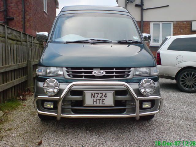
The spots on the bar are wired into a dedicated circuit, the fogs in the bumper are wired "the rooster way"
Posted: Sun Jan 13, 2008 9:41 pm
by bongo rbk
Yeah like that but without the big spots. I like BDC looking real good.
Are they the original fogs??