Page 1 of 1
Waeco Cruise - Nice Addition
Posted: Fri Jan 11, 2008 11:25 am
by BongoMTBer
Having fitted c/c just before Xmas, I was not totally happy with the control position (side of steering colum) and asthetics. Using 3 x panel mount switches and 1m of 9 wire video cable I had made rather a neat modification.
I mounted the three switches along side the gear selector and using the 9 wire cable soldered them to the back of the board on the control.
I now have cruise control easily accessable close to where I rest my hand on long jouneys and have been able to hide the waeco control out of sight

Well, it kept me busy for an hour or so.

Posted: Fri Jan 11, 2008 11:43 am
by scanner
Pictures?
Diagram?
I've been thinking of doing the same thing - I'd be happy with just Set and Resume.
Posted: Fri Jan 11, 2008 2:25 pm
by mikeonb4c
Yep before and after pics would be great

Posted: Fri Jan 11, 2008 2:48 pm
by BongoMTBer
Awe c'mon use some imagination!
Will see what I can do.

Before photos are not really an option now though.
These are the buttons though; off the shelf in Maplin as was the 9 wire video cable:
In black:
http://www.maplin.co.uk/Module.aspx?Tab ... 3&doy=11m1
Would have used these though if I had seen them:
http://www.maplin.co.uk/Module.aspx?Tab ... 2&doy=11m1
PROCEDURE
1, Remove central console
2, Unclip and remove black cowling off around gear selector
3, Drill three holes down LH side as close to the radiused edge of the cowel as possible. This will give clearance for the switches underneath.
4, Fit switches
5, Take apart controler
6, Solder 2 wires per controller sw. (will be obvious when you look at tracks on board where to solder)
7, Connect other end of each pair of wires to newly fitted switch
8, Refit cowling, route cable and refit console
8, Hide ugly grey controller
9, Done!
I did consider mounting a repeater for the LED in line with the switches, but the 12v LED I had would not work off the tapping off the controller board. I am sure it would work with a std micro LED though using the same wiring principle as the switches.
Posted: Fri Jan 11, 2008 10:24 pm
by BongoMTBer
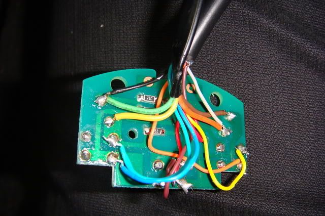
The wiring onto the controller board. Notice white and black wires onto green and orange. This is a 12v supply for a 12v LED.
Another six wires are soldered onto the teminals for the original switches.
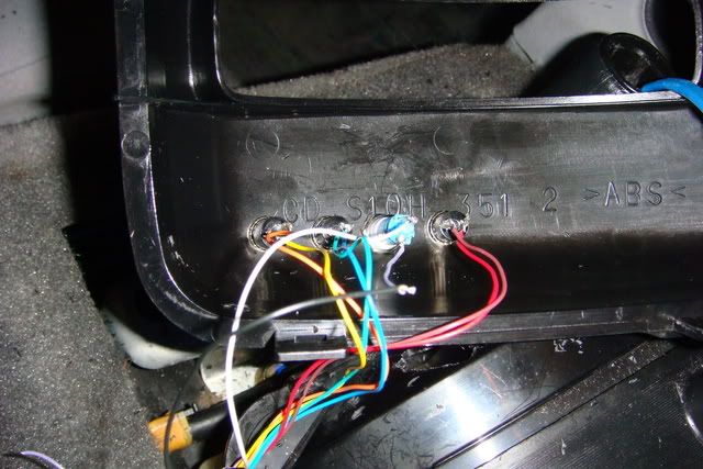
Holes drilled into the selector cowling and wires soldered onto switches and LED. Switches fitted.
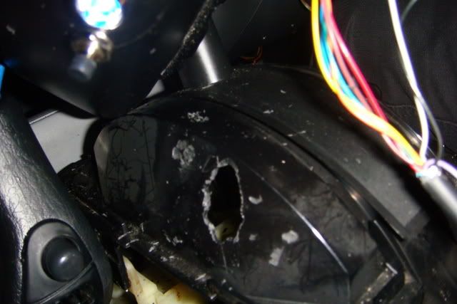
Due to the depth of the LED holder, I had to hack out a hole on the inner selector cowling. I wish I had used a hole cutter and bodged it like this!
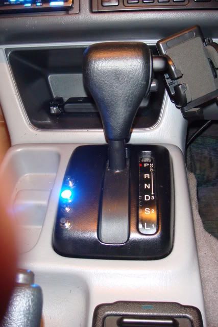
Nearly there. Just need to put the cowling back on.
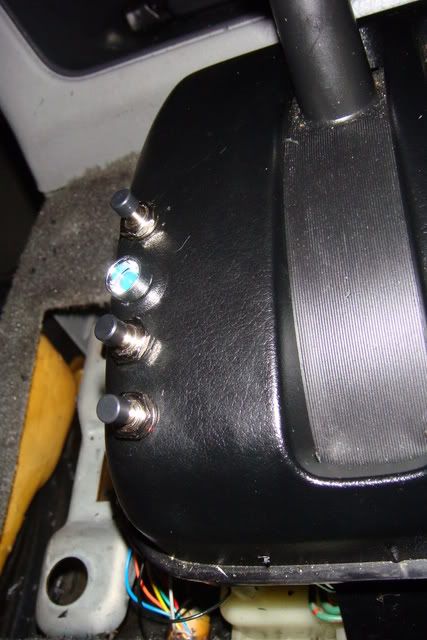
Done, and it works! The LED was too bright so I had some thick sticky tape which I carefully cut and placed a couple of layers over the LED to reduce brightnes.
Kept me off the road for a few hours so probably saved me the cost of parts in fuel
Posted: Sat Jan 12, 2008 1:52 am
by mikeonb4c
Ooh but that's neat. Wish I had one wot was like that.
Kept me off the road for a few hours so probably saved me the cost of parts in fuel
Often think the same myself - it doesnt take much running about to spend the same £ as a nice accessory would cost - seems ironic

Posted: Sat Jan 12, 2008 7:09 am
by BongoMTBer
Gladly help you do it one day Mike.