coolant flow - (follow up to cooling diagram)

Technical questions and answers about the Mazda Bongo

Moderators: Doone, westonwarrior

Locked
User avatar
widdowson2008
Supreme Being
Posts: 1703
Joined: Tue Nov 18, 2008 10:15 pm
Location: N.E.Derbyshire

Re: coolant flow - (follow up to cooling diagram)

Post by widdowson2008 » Mon Nov 22, 2010 1:35 pm

That's the bit I can't readily see without taking it apart, and can't do that cos I aint got a spare :wink:
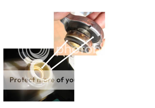
Are you really sure this cap has a vaccum valve? and if so, where might I find it?
More to the point, is my cap the correct one :lol:

edit - pic of the cap
Image
Steve
User avatar
mikexgough
Supreme Being
Posts: 6158
Joined: Mon Sep 08, 2008 9:02 pm
Location: Cambridgeshire - where the all the Slodgers reside
Contact:

Re: coolant flow - (follow up to cooling diagram)

Post by mikexgough » Mon Nov 22, 2010 2:08 pm

Ron Miel wrote: Simplification helps get first principles over but doesn't this only take account of two of the dynamic processes involved?

As well as any gradual coolant leaking causing this build up of air in the head and its pressurisation by combustion heat, progressive entraining of that air into coolant flowing by it will also gradually carry it off to the expansion tank, where the tank's inbuilt coolant vortexing/de-gassing compartments will separate it out from the coolant - causing an equal air build up and drop in coolant level in the ex tank but away from combustion processes.

In other words, although the topmost inner part of the head is a sealed high point where air will initially tend to collect, that doesn't mean that's then a static condition. That's what the second high revving stage (ex tank pressure cap re-fitted/system sealed) of the bleeding process is about. It works by entraining any small amounts of still trapped air anywhere in the system (including heaters, although probably less effectively due to the lesser air/coolant interface there) into coolant flow, to be carried away for de-gassing. Note that if there's still enough air trapped anywhere to cause a complete blockage, no amount of water pump pressure will clear it, so there will be no coolant flow and the de-gas process will not work. Hence the importance of carrying out earlier refill stages (cold fill, and bleed tube venting) very carefully first.

That overall de-gas process will only remove head-trapped air up to its system designed rate though, so in a more leaky engine a point will arrive where air collects in the head roof too fast to be carried away before causing progressive head overheating/weakening. Hence the need to keep all coolant connections as airtight as possible, to deal with even the smallest of detected leaks immediately (or stop driving), and to replace spongy hoses (they don't have to burst to slowly leak), etc. It also means that observed slow reductions of coolant level at the expansion tank should never be allowed to continue, and the cause(s) must quickly be found and rectified.
Spot on......
Conversant with Bongo Top Pinion Oil Seals

Bongo owning Velotech Cycle Mechanic
User avatar
dave_aber
Supreme Being
Posts: 2884
Joined: Tue May 12, 2009 4:33 pm
Location: Elgin, Scotland

Re: coolant flow - (follow up to cooling diagram)

Post by dave_aber » Mon Nov 22, 2010 2:45 pm

Are you really sure this cap has a vaccum valve?
Maybe it has, maybe it hasn't - however it doesn't work like the one in your link to 'how stuff works'.

My son's Toyota Starlet has the same arrangement as that animation, a pressurised radiator with a (in his case) 0.9 Barg cap which vents when over-pressurised into an overflow bottle. The vent pipe is always submerged in the coolant in this bottle, so when the cooling system 'sucks' back under cooling/contraction, it doesn't draw in air. (Presumably, any air in the system will collect under the cap, and be expelled into the bottle never to return?)

In our case, the expansion tank always has air in the top, up under the cap. Under overpressure situations, the cap lifts and the excess air pressure is let out. Whatever pressure builds up in the system, it won't exceed 1.1 Barg as the cap would let it out. When the system cools, the air in the header is at 1.1 Barg initially. As the coolant contracts, the air expands and lowers back to 0 Barg.

I'm sure a simple rig could be built to test if the cap will pass air when in a reverse pressure situation. This could also be tested by getting the coolant warm enough to raise the level in the tank, with the cap off, and then refitting it. Let the engine completely cool down, and remove the cap. If a partial vacuum can be heard equalising then the cap doesn't have a vac valve. If it doesn't suck air in, the it must have been doing it gradually through the cap....
Image...Image
There are 10 types of people in this world.
Those that understand binary, and those that don't.
User avatar
Northern Bongolow
Supreme Being
Posts: 7722
Joined: Mon Mar 15, 2010 11:33 pm
Location: AKA Vanessa

Re: coolant flow - (follow up to cooling diagram)

Post by Northern Bongolow » Mon Nov 22, 2010 3:43 pm

dave_aber wrote:
Are you really sure this cap has a vaccum valve?
Maybe it has, maybe it hasn't - however it doesn't work like the one in your link to 'how stuff works'.

My son's Toyota Starlet has the same arrangement as that animation, a pressurised radiator with a (in his case) 0.9 Barg cap which vents when over-pressurised into an overflow bottle. The vent pipe is always submerged in the coolant in this bottle, so when the cooling system 'sucks' back under cooling/contraction, it doesn't draw in air. (Presumably, any air in the system will collect under the cap, and be expelled into the bottle never to return?)

In our case, the expansion tank always has air in the top, up under the cap. Under overpressure situations, the cap lifts and the excess air pressure is let out. Whatever pressure builds up in the system, it won't exceed 1.1 Barg as the cap would let it out. When the system cools, the air in the header is at 1.1 Barg initially. As the coolant contracts, the air expands and lowers back to 0 Barg.

I'm sure a simple rig could be built to test if the cap will pass air when in a reverse pressure situation. This could also be tested by getting the coolant warm enough to raise the level in the tank, with the cap off, and then refitting it. Let the engine completely cool down, and remove the cap. If a partial vacuum can be heard equalising then the cap doesn't have a vac valve. If it doesn't suck air in, the it must have been doing it gradually through the cap....

spot on :lol: :lol: and also agree with rons comments, :lol: this is no good we are all starting to agree with each other. #-o :lol: :lol:
User avatar
dave_aber
Supreme Being
Posts: 2884
Joined: Tue May 12, 2009 4:33 pm
Location: Elgin, Scotland

Re: coolant flow - (follow up to cooling diagram)

Post by dave_aber » Mon Nov 22, 2010 3:46 pm

we are all starting to agree with each other.
:shock:

(Next we'll be agreeing with Bongo Forum!)
Image...Image
There are 10 types of people in this world.
Those that understand binary, and those that don't.
User avatar
Ron Miel
Supreme Being
Posts: 2239
Joined: Tue Oct 21, 2008 5:40 pm
Location: Cheshire

Re: coolant flow - (follow up to cooling diagram)

Post by Ron Miel » Mon Nov 22, 2010 4:12 pm

mikexgough wrote:
Spot on......
With grateful acknowledgment to the stuff you sent me on de-gassing particularly Mike. Might be worth providing a link to the very interesting Toyota patent on the subject, for anybody retired/with time on their hands, like Steve and I, and/or for pure Bongomasochists for that matter :lol:
2001-V6-LPG-AFT-black on silver-Imperial Purbeck camper

(Ron miel=honey rum from the Canaries)
User avatar
widdowson2008
Supreme Being
Posts: 1703
Joined: Tue Nov 18, 2008 10:15 pm
Location: N.E.Derbyshire

Re: coolant flow - (follow up to cooling diagram)

Post by widdowson2008 » Mon Nov 22, 2010 6:16 pm

dave_aber wrote:
Are you really sure this cap has a vaccum valve?
Maybe it has, maybe it hasn't - however it doesn't work like the one in your link to 'how stuff works'.
Actually, in principle, I think it does Dave. The one in the link is for a conventional cooling system and as such is fitted to the main radiator (thought I mentioned that????........ :oops: , perhaps not :oops: )
Got a phone call from a well respected member who explained it, and I missed it when I was measuring it (well hidden). That's 2 people who think this way, and I aint going against that sort of current :P
Take a look again at the pic I posted earlier today. The brassy looking domed bit on the underside of the cap. Apparently, if you separate this from the bottom seal and give it a tug, guess what's behind? The second (hidden) spring. Not actually physically seem it - put my cap back on before I got the call and as it was persisting it down, didn't go and retrieve it. I DO however have a great deal of respect for the guy who alerted me to this little well hidden secret.

Produced animation to show it (it's just off to be confirmed at the moment)
Last edited by widdowson2008 on Mon Nov 22, 2010 6:28 pm, edited 1 time in total.
Steve
bigdaddycain
Supreme Being
Posts: 10637
Joined: Fri May 13, 2005 11:58 am
Location: Ince Lancs

Re: coolant flow - (follow up to cooling diagram)

Post by bigdaddycain » Mon Nov 22, 2010 6:27 pm

dave_aber wrote:
we are all starting to agree with each other.
:shock:

(Next we'll be agreeing with Bongo Forum!)
[-X [-X [-X
ビッグダディケイン RIP Big Bank Hank (Imp the Dimp) 1957-2014
User avatar
widdowson2008
Supreme Being
Posts: 1703
Joined: Tue Nov 18, 2008 10:15 pm
Location: N.E.Derbyshire

Re: coolant flow - (follow up to cooling diagram)

Post by widdowson2008 » Mon Nov 22, 2010 6:51 pm

Image
Steve
User avatar
dave_aber
Supreme Being
Posts: 2884
Joined: Tue May 12, 2009 4:33 pm
Location: Elgin, Scotland

Re: coolant flow - (follow up to cooling diagram)

Post by dave_aber » Mon Nov 22, 2010 7:02 pm

Actually, in principle, I think it does Dave
Hate to say this, but I have to agree :D . What I meant was that the overall header tank bit differs in that ours vents air, and the animation is all about venting water. The cap specifically does operate identically. Your latest pic demonstrates how it does it perfectly (I did wonder how the water got back into the system on my lad's car!)
Image...Image
There are 10 types of people in this world.
Those that understand binary, and those that don't.
User avatar
widdowson2008
Supreme Being
Posts: 1703
Joined: Tue Nov 18, 2008 10:15 pm
Location: N.E.Derbyshire

Re: coolant flow - (follow up to cooling diagram)

Post by widdowson2008 » Mon Nov 22, 2010 7:14 pm

dave_aber wrote:
Actually, in principle, I think it does Dave
......, but I have to agree :D .
Thank the Lord for that - couldn't cope if you disagreed - would mean I'd got it wrong :shock: :wink:

Have you ever considered (something I do a hell of a lot when studying this sort of thing), just how many ACTUAL components are thrutching up and down, spinning round, etc, all at vast speeds, each time you start the Bongo? and they all have to work together :shock:
Steve
User avatar
Ron Miel
Supreme Being
Posts: 2239
Joined: Tue Oct 21, 2008 5:40 pm
Location: Cheshire

Re: coolant flow - (follow up to cooling diagram)

Post by Ron Miel » Mon Nov 22, 2010 7:36 pm

Add to that all the bits inside of us that have got to instantaneously work together to see, hear, feel, smell, think, push, pull and drive the jolly thing, and you can only conclude aint life wonderful 8)
2001-V6-LPG-AFT-black on silver-Imperial Purbeck camper

(Ron miel=honey rum from the Canaries)
User avatar
dave_aber
Supreme Being
Posts: 2884
Joined: Tue May 12, 2009 4:33 pm
Location: Elgin, Scotland

Re: coolant flow - (follow up to cooling diagram)

Post by dave_aber » Mon Nov 22, 2010 7:56 pm

Contrast the Bongo with the humble 2CV. The engine has 24 seperate moving parts - and one of them is the oil.
Image...Image
There are 10 types of people in this world.
Those that understand binary, and those that don't.
User avatar
mikexgough
Supreme Being
Posts: 6158
Joined: Mon Sep 08, 2008 9:02 pm
Location: Cambridgeshire - where the all the Slodgers reside
Contact:

Re: coolant flow - (follow up to cooling diagram)

Post by mikexgough » Mon Nov 22, 2010 8:16 pm

dave_aber wrote:Contrast the Bongo with the humble 2CV. The engine has 24 seperate moving parts - and one of them is the oil.
Oh yes..... now that is a great car.....and the engine is just superb.... Got plenty of parts still :roll:
Conversant with Bongo Top Pinion Oil Seals

Bongo owning Velotech Cycle Mechanic
User avatar
dandywarhol
Supreme Being
Posts: 5446
Joined: Mon Dec 19, 2005 10:18 pm
Location: Edinburgh

Re: coolant flow - (follow up to cooling diagram)

Post by dandywarhol » Mon Nov 22, 2010 9:15 pm

widdowson2008 wrote:Image
Got in one! :D nice animation - rad caps have been doing exactly that for yonks - its mainly to prevent the hoses collapsing (imploding)

I've known of "mechanics" to have replaced in the following order to solve an overheating problem..........

Thermostat first
Water pump
Radiator
Head gasket

...............and still the engine overheated - what he had omitted to check (through lack of understanding his job) was the radiator cap seal !!! :?

If the system can't pressurise then the coolant boils at 108 or so deg (depending on antifreeze type/strength) the unpressurised coolant soon turns to steam!
Whale oil beef hooked
Renault Lunar Telstar
Yamaha TD1C 250, Merc SLK200, KTM Duke 690
Locked

Return to “Techie Stuff”