Page 30 of 41
Re: coolant flow - (follow up to cooling diagram)
Posted: Thu Nov 18, 2010 10:08 am
by Ron Miel
Surely it's a question of degree, if not semantics. Room for design improvement, anyway - hence the 2001 head re-design for other applications of this Ford engine?
I think the whole thread does still point up the benefits of using the full Mazda-specified air bleed procedure for re-filling after any drain down which introduces air into the upper levels of the system - even though, with luck, a following wind, a good fast reacting coolant temperature monitor,
and very careful attention, the engine idling/self-bleeding/automatic de-gassing method can also be made to work. Whether every time is another matter, and I reckon the jury's out, unless a lot more peeps are persuaded to try it first - I wouldn't, particularly not in my V6 (see below).
The coolant flows highlighted here
http://www.igmaynard.co.uk/bongo/forum/ ... 02#p457197 confirm, once again, that the front heater is particularly tricky to bleed. Routing of coolant from there, through a switchback of plumbing before it eventually gets round to the expansion/de-gassing tank (as it really is) means that trapped air in the heater will be particularly slow to fully shift by transfer to the ex tank for eventual venting by topping up there - unless the high revving Mazda method is used.
These observations are based on recent direct experience, as well as a number of PM exchanges with two other peeps with related experience, careful reading of this brilliant topic, and independent reading. Other points which have emerged, with reference to the V6 J5 petrol engine, are:
1.) The Mazda-recommended (instructed!) bleed method for the J5 engine takes longer than that for the WL-T diesel - perhaps unsurprisingly, given the two banked cylnder heads of the V6 (although we presumably don't know if there are air trapping areas at the top of them as in the WL-T's single head).
2.) When self-bled, the V6 seems* to take a lot longer to circulate entrapped air for eventual venting by topping up coolant at the ex tank - again perhaps not altogether surprisingly. I would therefore definitely not recommend it on a V6, at least not before there have perhaps been more guinea pigs.
*(Although my LPG conversion could possibly also be relevant here - coolant flows through parts of it. Anyway, be assured that I haven't deliberately self-bled my V6! It has been done by default, after a "Bongo-friendly" garage did not use the bleed (vent) hose method after a coolant change, and left me unwittingly completing a self-bleed process. I've been able to compare results/timing with another peep whose WL-T engine was given the same treatment at the same place.)
Re: coolant flow - (follow up to cooling diagram)
Posted: Thu Nov 18, 2010 11:08 am
by dave_aber
Amazing what you can learn with a bit of Google.
According to
Trouton's Rule, a liquid which boils at 109° when at 1Bar will boil at 112.37° at 1.1Bar.
However, it's occurred to me that my son's car has a 0.9 bar cap - what I take from this is that our 1.1bar caps mean that the actual boiling pressure is 1.1 bar above atmospheric - i.e. 2.1 Bar. At this pressure, the boiling point would be 136.9° for a liquid which boils at 109° when at atmospheric.
Re: coolant flow - (follow up to cooling diagram)
Posted: Thu Nov 18, 2010 11:22 am
by haydn callow
isn't Atmospheric pressure 0 ??? at sea level
Re: coolant flow - (follow up to cooling diagram)
Posted: Thu Nov 18, 2010 11:44 am
by Ron Miel
That's a vacuum.
Re: coolant flow - (follow up to cooling diagram)
Posted: Thu Nov 18, 2010 11:54 am
by dave_aber
No, atmospheric is 1Bar.
Tyre pressures, radiator caps, etc are usually measured as pressure compared to atmospheric - so a tyre at 1Bar is really at 1 Bar above atmospheric, i.e. 2Bar.
Absolute pressure and gauge pressure
Bourdon tube pressure gauges, vehicle tire gauges, and many other types of pressure gauges are zero referenced to atmospheric pressure, which means that they measure the pressure above atmospheric pressure (which is around 1 bar); this is gauge pressure and is often referred to as barg (spoken "bar gauge"). In contrast, absolute pressures are zero referenced to a complete vacuum and when expressed in bar are often referred to as bara. Thus, the absolute pressure of any system is the gauge pressure of the system plus atmospheric pressure. The usage of bara and barg is now deprecated, with qualification of the physical property being preferred, e.g., "The gauge pressure is 2.3 bar; the absolute pressure is 3.3 bar".[2]
In the United States, where pressures are still often expressed in pounds per square inch (symbol psi), gauge pressures are referred to as psig and absolute pressures are referred to as psia. Gauge pressure is also sometimes spelled as gage pressure.
Sometimes, the context in which the word pressure is used helps to identify it as meaning either the absolute or gauge pressure. However, in truth, whenever a pressure is expressed in any units (bar, Pa, psi, atm, etc.), it should be denoted in some manner as being either absolute or gauge pressure to avoid any possible misunderstanding. One recommended way of doing so is to spell out what is meant, for example as bar gauge or kPa absolute.[6]
Re: coolant flow - (follow up to cooling diagram)
Posted: Thu Nov 18, 2010 12:06 pm
by haydn callow
Well there you go ....so my 1.1 bar pressure cap actually "blows" at 2.1 Bar
Re: coolant flow - (follow up to cooling diagram)
Posted: Thu Nov 18, 2010 12:24 pm
by dave_aber
2.1 bara or 1.1barg.
The spring in it pushes at 1.1 bar. The air outside pushes at another 1 bar, so the water inside needs to push at 2.1 bar.
Re: coolant flow - (follow up to cooling diagram)
Posted: Thu Nov 18, 2010 12:58 pm
by widdowson2008
Getting back to subject of the topic, has anyone noticed something odd/different about these two flow paths?

This path goes from the block to the glow plug (very hot) to the inlet valve (not so hot) and out of the head through the main chamber.

This path goes from the block to the exhaust valve (very hot) to the inlet valve (not so hot) and out of the head through the main chamber.
Struck me that the designers could be trying to balance temperature of the two sides of the head in an attempt to reduce the temperature difference between the two. Why? To cut down the possibility of cracks due to thermal shock (Hot meets Cold)?
Re: coolant flow - (follow up to cooling diagram)
Posted: Thu Nov 18, 2010 2:48 pm
by dandywarhol
Pressurised WATER boiling point is raised approx. 1.5 deg. C for every 1 psi of pressure - antifreeze mix raises the BP too
Re: coolant flow - (follow up to cooling diagram)
Posted: Thu Nov 18, 2010 3:09 pm
by dave_aber
So (sorry Steve, I'm off on a tangent again), 1.1 Bar = 15.96psi equates to 23.25° increase. So, a 109° fluid would boil at 132.25°@1.1 Barg. Add a wee bit for the antifreeze, seems to correlate close enough to the web page I found earlier.
No wonder it hurts when you take the cap off still pressurised!
Re: coolant flow - (follow up to cooling diagram)
Posted: Thu Nov 18, 2010 3:56 pm
by mikexgough
dave_aber wrote:So (sorry Steve, I'm off on a tangent again), 1.1 Bar = 15.96psi equates to 23.25° increase. So, a 109° fluid would boil at 132.25°@1.1 Barg. Add a wee bit for the antifreeze, seems to correlate close enough to the web page I found earlier.
No wonder it hurts when you take the cap off still pressurised!
Nice work dave...... so that raises the game a little for the "Green" corner.... so I guess the "red" corner would achieve similar results...... what interested me was from my chemist pal, he was saying that silicates in coolant leave a deposit on the waterways (bit like a film) over time and hot/cold cycles....leading to an "insulation" effect and the theory there is that hot spots could occur......
I have not found anyone to say exactly what causes the head failures on these Ford engines but if you put all the ideas together all the answer seems to be the correct maintanence.
The Truck guys (with the same engine)who have the overheating bothers all blame the coolant type and thermostat.....those with camshafts go blame their engine oils.....
I guess this whole process is an investigation as to how it all works in a Bongo/Freda, but at least we know the head crack issue is not Bongo/Freda specific .
Now Steve has produced all these diagrams, I guess a "review" is needed to put it all together.
Re: coolant flow - (follow up to cooling diagram)
Posted: Thu Nov 18, 2010 5:15 pm
by dandywarhol
dave_aber wrote:So (sorry Steve, I'm off on a tangent again), 1.1 Bar = 15.96psi equates to 23.25° increase. So, a 109° fluid would boil at 132.25°@1.1 Barg. Add a wee bit for the antifreeze, seems to correlate close enough to the web page I found earlier.
No wonder it hurts when you take the cap off still pressurised!
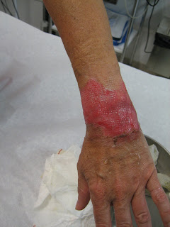
Aye - this is what happened after a kettle of just of the boil water did - and that was a week after the event! 132 deg of sticky coolant is unimaginable

I stupidly removed a cap off a Hillman Imp with a blown head gasket many moons ago and when I removed my soaked tee shirt all the skin on my arm and half of my chest came off with it - only 1st deg burn - Carole's wrist was 2nd degree!
Moral of story - let the pressure off first!
Re: coolant flow - (follow up to cooling diagram)
Posted: Thu Nov 18, 2010 5:22 pm
by dave_aber
Ouch!
Almost as bad as Barrington's finger.
Re: coolant flow - (follow up to cooling diagram)
Posted: Fri Nov 19, 2010 9:44 am
by widdowson2008
2nd attempt
widdowson2008 wrote:Getting back to subject of the topic, has anyone noticed something odd/different about these two flow paths?
This path goes from the block to the glow plug (very hot) to the inlet valve (not so hot) and out of the head through the main chamber.
This path goes from the block to the exhaust valve (very hot) to the inlet valve (not so hot) and out of the head through the main chamber.
Struck me that the designers could be trying to balance temperature of the two sides of the head in an attempt to reduce the temperature difference between the two. Why? To cut down the possibility of cracks due to thermal shock (Hot meets Cold)?
Re: coolant flow - (follow up to cooling diagram) BLEEDING
Posted: Sat Nov 20, 2010 3:36 pm
by widdowson2008
Looks like the flows through the head has got others as baffled as me. (or possiblly not interested?)
So, I think the subject line, 'COOLANT FLOW' is exhausted. I'm pretty confident with what we have found out. Thanks for all your help.
Just leaves one area not discussed fully (based on known facts), and more to the point, I suspect one not totally understood by the majority of folk - me included. Seen it done but not fully understood what I was looking at.
I make no apologies for bringing up this old chestnut, (it is a major part of the cooling system) but I believe that knowledge to date has been based on guesswork and the 'I know better' attitude.
Personally, I need to understand how things work, not just take someone elses word for it.
What is the subject? BLEEDING.
Reason for bringing it up is that I think I may have a very simple solution to the black art (based on factual knowledge gained in this thread). Can't think how no one has thought of it before. (or perhaps they have)
I'LL BE BACK!!!

for all your hard work.i must just say,that in my humble opinion,i hasnt really pointed to a head design fault. or has it.