


The reason I'm emphasising all this, is that if you bleed your car on a completely level surface, and if you don't do anything else, you'll end up with about half a litre of air in the top of the head. BUT... you can have most of that air disappear by including in your bleeding process, one or two very easy ways.
If you jack up your front passenger quarter just a bit while bleeding, or if you rock your car a bit at the appropraiate time, you can cut that air down considerably. Especially if you do this late in the bleeding process, with a warm engine running.
coolant flow - (follow up to cooling diagram)
Moderators: Doone, westonwarrior
-
mikexgough

- Supreme Being
- Posts: 6158
- Joined: Mon Sep 08, 2008 9:02 pm
- Location: Cambridgeshire - where the all the Slodgers reside
- Contact:
Re: coolant flow - (follow up to cooling diagram)
Been out and measured mine.....widdowson2008 wrote: Just been out to check and in fact the Xtank is shown a little too high, but not much.
The dimensions on my Bongo are:
Floor to extreme top of radiator = 970mm
Floor to bottom of expansion tank = 930/935 (not easy to get a direct reading due to curvature on bottom edge of X/tank )
This means that when the radiator is full to the top (to the point of overflowing), there will be a depth of 35/40mm of coolant in the expansion tank..
Conversant with Bongo Top Pinion Oil Seals
Bongo owning Velotech Cycle Mechanic
Bongo owning Velotech Cycle Mechanic
-
widdowson2008

- Supreme Being
- Posts: 1703
- Joined: Tue Nov 18, 2008 10:15 pm
- Location: N.E.Derbyshire
Re: coolant flow - (follow up to cooling diagram)
.....centre of inlet? Didn't think there was an external INLET to the headFredalier wrote:
Also, relative heights of coolant inlet to head and outlet from head are not quite right. The centre of outlet is 80mm below rocker cover gasket: centre of inlet is 84mm below rcg. The ceiling of the water chamber inside the head is 57mm below rocker cover gasket.
....If you jack up your front passenger quarter just a bit while bleeding
1 - to the thermostat
2 - to the radiator (top hose)
.....jack up your front passenger? Agree with this, especially if you look at a post by Bongonads (cant put my hands on it
Also, looking at the relative component heights, it appears that you would get more coolant OUT when draining if you jacked the back of the van up.
Could you also clarify the 80mm and 57mm dimensions please? Not doubting them, just wondering how accurate they are and how you got them. Have you 'split' a head open at some time?
Steve
-
widdowson2008
- Supreme Being
- Posts: 1703
- Joined: Tue Nov 18, 2008 10:15 pm
- Location: N.E.Derbyshire
Re: coolant flow - (follow up to cooling diagram)
High/low markers are both ABOVE 35mm from tank bottom and ABOVE the larger tank inlet.mikexgough wrote:Been out and measured mine.....widdowson2008 wrote: Just been out to check and in fact the Xtank is shown a little too high, but not much.
The dimensions on my Bongo are:
Floor to extreme top of radiator = 970mm
Floor to bottom of expansion tank = 930/935 (not easy to get a direct reading due to curvature on bottom edge of X/tank )
This means that when the radiator is full to the top (to the point of overflowing), there will be a depth of 35/40mm of coolant in the expansion tank..I follow what you are saying Steve with the data...... just getting my head around how the 35ish mm relates to the high/low parameters in the tank......i.e where 35ish mm is on the guide markers if at all....(might have another look later after the ..........rain
yep rain.....stops)
The bottom, (6mm) x/tank connection is actually at the extreme bottom of the tank as can be seen from the 3rd attached pic, and this is below the top of the radiator - hence my reasoning that when the rad is filled to the brim, the x/tank gets its floor covered.
For interest (mine really) I have thrown another 2 pics of the x/tank which I took whilst the wife was out walking. And yes, that is my gut you can see in the background.


Steve
-
haydn callow

- Supreme Being
- Posts: 5778
- Joined: Mon Jan 08, 2007 9:50 pm
- Location: Somerset
- Contact:
Re: coolant flow - (follow up to cooling diagram)
Time for a Mod to step in me thinks.......
-
francophile1947
- Supreme Being
- Posts: 11354
- Joined: Mon Dec 18, 2006 6:15 pm
- Location: Norwich
Re: coolant flow - (follow up to cooling diagram)
OK folks - settle down now or we'll never discover the truth
I've deleted all of the irrelevant and argumentative posts, as they serve no useful purpose whatsoever.
I've deleted all of the irrelevant and argumentative posts, as they serve no useful purpose whatsoever.
John
(Evidence that intelligent life exists in the universe, is that it hasn't tried to contact us)
(Evidence that intelligent life exists in the universe, is that it hasn't tried to contact us)
-
Northern Bongolow

- Supreme Being
- Posts: 7724
- Joined: Mon Mar 15, 2010 11:33 pm
- Location: AKA Vanessa
Re: coolant flow - (follow up to cooling diagram)
dont know how relavant this may be,but out of the bongos ive bled,which is a few,tipping the motor,either one way or another to bleed doesnt really seem to help in the final push.if you tip it one way it gets caught in another spot,ie the front heater matrix.the method i use is as per the video.if there is another way that helps im all ears.the key is to remove the bleed pipe bung before filling.
-
mikexgough
- Supreme Being
- Posts: 6158
- Joined: Mon Sep 08, 2008 9:02 pm
- Location: Cambridgeshire - where the all the Slodgers reside
- Contact:
Re: coolant flow - (follow up to cooling diagram)
Northern Bongolow wrote:the key is to remove the bleed pipe bung before filling.
exactly...... if not the bleed process will be a nightmare and why many have trouble........
bleed as much air out when the engine is cold as with ANY engine......then there is little air left to bleed to clear the system..... Jobs a good 'un
I guess others have their methods which work for them...... I have mine......but the main thing to get right is the above, clear as much air when the motor is cold....
As for the expansion tank.......good stuff Steve....
Conversant with Bongo Top Pinion Oil Seals
Bongo owning Velotech Cycle Mechanic
Bongo owning Velotech Cycle Mechanic
-
widdowson2008
- Supreme Being
- Posts: 1703
- Joined: Tue Nov 18, 2008 10:15 pm
- Location: N.E.Derbyshire
Re: coolant flow - (follow up to cooling diagram)
I took sandstones 'side view' (with his kind permission and assistance) seen here
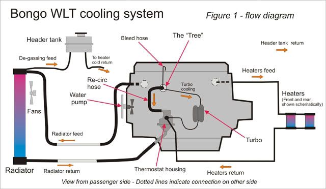
NOTE: The flow shown is when the thermostat is partly open. More to follow later showing what happens in the various stat positions.
Thanks to sandstone for his input.
I think its there, or thereabouts, but if anyone would like to offer further ideas they will be gratefully received.

Added a couple of details, repositioned stuff to be a little nearer (geographically) and came up with this animated version in the hope that it explains things a bit easier.sandstone wrote:.........However, have got back to find a good animation which helps in understand the dynamic nature of the cooling circuits.
.
NOTE: The flow shown is when the thermostat is partly open. More to follow later showing what happens in the various stat positions.
Thanks to sandstone for his input.
I think its there, or thereabouts, but if anyone would like to offer further ideas they will be gratefully received.
Steve
-
Northern Bongolow
- Supreme Being
- Posts: 7724
- Joined: Mon Mar 15, 2010 11:33 pm
- Location: AKA Vanessa
Re: coolant flow - (follow up to cooling diagram)
ooooooooooohhhhhhhhhhhhhh
i do like that.
can i have the pump spinning please steve or is that just being greedy.
seriously----excellent
i do like that.
can i have the pump spinning please steve or is that just being greedy.
seriously----excellent
-
mikexgough
- Supreme Being
- Posts: 6158
- Joined: Mon Sep 08, 2008 9:02 pm
- Location: Cambridgeshire - where the all the Slodgers reside
- Contact:
Re: coolant flow - (follow up to cooling diagram)
nice work almost done with my bits too - if this rain keeps up in Cornwall, you will have them sooner than I thought
Conversant with Bongo Top Pinion Oil Seals
Bongo owning Velotech Cycle Mechanic
Bongo owning Velotech Cycle Mechanic
-
widdowson2008
- Supreme Being
- Posts: 1703
- Joined: Tue Nov 18, 2008 10:15 pm
- Location: N.E.Derbyshire
Re: coolant flow - (follow up to cooling diagram)
You're pushing it a bit there Ady..........oh go on then. I'll have a go.Northern Bongolow wrote:ooooooooooohhhhhhhhhhhhhh
i do like that.
can i have the pump spinning please steve or is that just being greedy.
seriously----excellent
However, I'm drawing the line at wing mirrors.
Edit - an earlier request. Sorry about pump Ady. Not easy from the side.

Steve
-
widdowson2008
- Supreme Being
- Posts: 1703
- Joined: Tue Nov 18, 2008 10:15 pm
- Location: N.E.Derbyshire
Re: coolant flow - (follow up to cooling diagram)
Sat up late to finish this (smarten it up). Please dont find owt wrong. 

Steve
-
haydn callow
- Supreme Being
- Posts: 5778
- Joined: Mon Jan 08, 2007 9:50 pm
- Location: Somerset
- Contact:
Re: coolant flow - (follow up to cooling diagram)
confused Steve...you've swapped the colours round ???
Cold into the rad...hot out ??
Ah.....feed/return.....getting it now.....
Cold into the rad...hot out ??
Ah.....feed/return.....getting it now.....
Last edited by haydn callow on Thu Aug 26, 2010 9:40 am, edited 1 time in total.
-
tomheaney99
Re: coolant flow - (follow up to cooling diagram)
Thats a work of art! most impressed!!! well done 