


For heat test results, see
http://www.igmaynard.co.uk/bongo/forum/ ... =3&t=41176
coolant flow - (follow up to cooling diagram)
Moderators: Doone, westonwarrior
-
widdowson2008

- Supreme Being
- Posts: 1703
- Joined: Tue Nov 18, 2008 10:15 pm
- Location: N.E.Derbyshire
-
widdowson2008
- Supreme Being
- Posts: 1703
- Joined: Tue Nov 18, 2008 10:15 pm
- Location: N.E.Derbyshire
Re: coolant flow - (follow up to cooling diagram)
OK, a little OTT, but this is my latest offering on the circuit diagram. (and it works for me)
The diagram is showing the stat open part way, but not fully. ie: flow from both head and rad.
Please take a look. What I would like to know is:
1 - do you understand it?
2 - are there any errors?
(gets back into bunker and waits for bullets)

The diagram is showing the stat open part way, but not fully. ie: flow from both head and rad.
Please take a look. What I would like to know is:
1 - do you understand it?
2 - are there any errors?
(gets back into bunker and waits for bullets)
Steve

Re: coolant flow - (follow up to cooling diagram)
That made me chuckle.
Excellent diagram though. Much clearer to see what's going where with the animation. Good effort.
Excellent diagram though. Much clearer to see what's going where with the animation. Good effort.


Re: coolant flow - (follow up to cooling diagram)
I know its been a while since I've been into London, but they have changed the UG a bit haven't they 
Geoff
2001 Aero V6, AFT, full side conversion.
2001 Aero V6, AFT, full side conversion.
-
widdowson2008
- Supreme Being
- Posts: 1703
- Joined: Tue Nov 18, 2008 10:15 pm
- Location: N.E.Derbyshire

-
mister munkey

- Supreme Being
- Posts: 5184
- Joined: Mon Oct 01, 2007 9:11 pm
- Location: Not Far From Royston Vasey, West Yorkshire
- Contact:
Re: coolant flow - (follow up to cooling diagram)
From a laymans point of view I reckon that's 1st Class.
Crystal.

Crystal.
The only true wisdom is in knowing you know nothing. http://www.travelblog.org/Bloggers/MisterMunkey
-
widdowson2008
- Supreme Being
- Posts: 1703
- Joined: Tue Nov 18, 2008 10:15 pm
- Location: N.E.Derbyshire
Re: coolant flow - (follow up to cooling diagram)
Thank you. It's the folk that don't know what's what that I am aiming for.mister munkey wrote:From a laymans point of view I reckon that's 1st Class.
Crystal.
If you understand that bit, it's worth doing the explanation in this format.
I'm doing summat for Ady to try and show what actually happens INSIDE when the bleeding process is taking place and why the various stages explained in Chells recent video are important.
Steve
-
Grahame at work
- Bongolier
- Posts: 330
- Joined: Fri Sep 30, 2005 12:43 pm
- Location: Aberdeen
Re: coolant flow - (follow up to cooling diagram)
I think thats great
only comment is would it help the layman to label the engine oil cooler?
Regrads Grahame
only comment is would it help the layman to label the engine oil cooler?
Regrads Grahame
Joanie2 has had a sex change and is remaned Bert
-
widdowson2008
- Supreme Being
- Posts: 1703
- Joined: Tue Nov 18, 2008 10:15 pm
- Location: N.E.Derbyshire
Re: coolant flow - (follow up to cooling diagram)
Hi GrahameGrahame at work wrote:I think thats great
only comment is would it help the layman to label the engine oil cooler?
Regrads Grahame
Not finished yet. Intend to FULLY label end product + a few other awesome goodies I'm learning on the new software.
Just at the 'consumer feedback' stage at the moment. Waste of time persuing it if folk can't understand the bloody thing.
Sent you a pm on semi-related topic,
Steve
-
mister munkey
- Supreme Being
- Posts: 5184
- Joined: Mon Oct 01, 2007 9:11 pm
- Location: Not Far From Royston Vasey, West Yorkshire
- Contact:
Re: coolant flow - (follow up to cooling diagram)
Its quite hypnotic if you stare at it for long enough.
Could make a cool subliminaly educational screensaver too!
Could make a cool subliminaly educational screensaver too!
The only true wisdom is in knowing you know nothing. http://www.travelblog.org/Bloggers/MisterMunkey

Re: coolant flow - (follow up to cooling diagram)
I posted in April about the control principles for the Bongo cooling system, and there was a query what did I mean by re-circ flow. Been off the forum for some time so have not been able to reply. However, have got back to find a good animation which helps in understand the dynamic nature of the cooling circuits.
Last year in France I replaced a burst hose and got a good description of the bleed process off the forum. However, there was a mass of material to wade though in trying to undertand:
1. The reasons for bleeding,
2. How the cooling system actually works
So I considered how the system is built, and ended writing the following, (with a view to becoming part of a fact sheet), which explains what I understand as the control principles.
So here it is, and maybe it can have some peer review.
--------
Bongo Cooling System
Control principle
The Bongo WLT diesel engine uses a "constant inlet temperature" system, which may be strange to those familiar with the family saloon with a thermostat on the outlet (eg; “constant outlet temperature” system) but it has been used for very good reasons which are explained later. See Fig 1 when reading the following text.
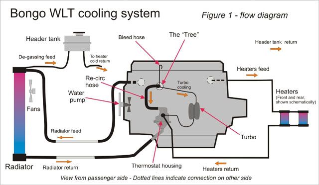
The constant inlet temperature control is obtained by placing the thermostatic valve within a mixing chamber on the engine coolant inlet. The re-circulation hose from the top of the block to the thermostat allows the thermostat to continually sense the engine water temperature. The thermostat’s sensing capsule is situated in a mixing chamber, in which the re-circulation line, the heater return and the radiator return can all mix and influence the opening of the valve.
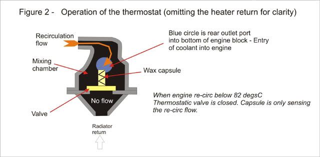
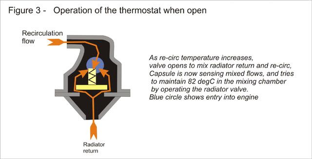
Initially on warm-up the valve is closed, so the only influence on the capsule is the re-circ line and heater returns. When the temperature in the mixing chamber reaches 82 C, the valve will start to open, and additional cool fluid is gradually admitted from the radiator circuit. With increasing engine coolant temperature the thermostat opens until equilibrium is reached and the mix of the three flows settle at somewhere above 82 C in the chamber. The exact temperature will vary a few degrees depending on flows and the thermostat’s response curve, but it can be considered practically as being “constant temperature” control. The re-circ flow will decrease as the thermostat opens.
Changes in engine heating load or cooling effect from heaters and radiator are sensed by the thermostat capsule. For instance; if the heat generated in the engine increases, so will the re-circ temperature, thus opening the valve further. If the ex-radiator coolant temperature drops, then the valve responds to reduce the flow.
This arrangement allows the engine and heater system to get to operating temperature as quickly as possible on start-up.
Fig 2 shows the flows within the thermostat housing when in full re-circulation. Note that the exit flow to the engine is through the cast pipe at the back. Fig 3 shows flows when mixed inlet flows are being sensed.
Constant inlet versus constant outlet control
The constant inlet temperature system has the advantage of giving a tighter temperature control on fluid entering the engine than the "constant outlet temperature" type of control (where the thermostat is on the engine outlet). An outlet control system can only sense the temperature of coolant after it has passed through the engine, when it is too late. Surges of cold fluid, such as when engine speed increases, when ex-radiator coolant temperature drops, or when the thermostat first opens, results in thermal shock to the engine. The Bongo constant inlet temperature system eliminates this.
Implications for air locking of cooling system design
The Bongo has low level pipes feeding the radiator because of the layout of the bodywork. This inhibits the purging of air out of the head, which can cause air locking and subsequent overheating.
The bleed pipe allows the following two crucial bleed operations:
1. When initially filling it bleeds air trapped in the cylinder head.
2. When warming up it allows air released by the opening thermostat to exit the system.
After a coolant system re-fill, the initial opening of the thermostat on warm-up is the point at which retained air in the radiator/thermostat hose is released into the engine and can be trapped in the head. This is when the thermostat opens and the bottom hose get warm. But a considerable coolant velocity would be required to force the large air bubble in the head down the main engine outlet hose and into the radiator. This may not be achieved, so the bleed process is necessary.
Last year in France I replaced a burst hose and got a good description of the bleed process off the forum. However, there was a mass of material to wade though in trying to undertand:
1. The reasons for bleeding,
2. How the cooling system actually works
So I considered how the system is built, and ended writing the following, (with a view to becoming part of a fact sheet), which explains what I understand as the control principles.
So here it is, and maybe it can have some peer review.
--------
Bongo Cooling System
Control principle
The Bongo WLT diesel engine uses a "constant inlet temperature" system, which may be strange to those familiar with the family saloon with a thermostat on the outlet (eg; “constant outlet temperature” system) but it has been used for very good reasons which are explained later. See Fig 1 when reading the following text.
The constant inlet temperature control is obtained by placing the thermostatic valve within a mixing chamber on the engine coolant inlet. The re-circulation hose from the top of the block to the thermostat allows the thermostat to continually sense the engine water temperature. The thermostat’s sensing capsule is situated in a mixing chamber, in which the re-circulation line, the heater return and the radiator return can all mix and influence the opening of the valve.
Initially on warm-up the valve is closed, so the only influence on the capsule is the re-circ line and heater returns. When the temperature in the mixing chamber reaches 82 C, the valve will start to open, and additional cool fluid is gradually admitted from the radiator circuit. With increasing engine coolant temperature the thermostat opens until equilibrium is reached and the mix of the three flows settle at somewhere above 82 C in the chamber. The exact temperature will vary a few degrees depending on flows and the thermostat’s response curve, but it can be considered practically as being “constant temperature” control. The re-circ flow will decrease as the thermostat opens.
Changes in engine heating load or cooling effect from heaters and radiator are sensed by the thermostat capsule. For instance; if the heat generated in the engine increases, so will the re-circ temperature, thus opening the valve further. If the ex-radiator coolant temperature drops, then the valve responds to reduce the flow.
This arrangement allows the engine and heater system to get to operating temperature as quickly as possible on start-up.
Fig 2 shows the flows within the thermostat housing when in full re-circulation. Note that the exit flow to the engine is through the cast pipe at the back. Fig 3 shows flows when mixed inlet flows are being sensed.
Constant inlet versus constant outlet control
The constant inlet temperature system has the advantage of giving a tighter temperature control on fluid entering the engine than the "constant outlet temperature" type of control (where the thermostat is on the engine outlet). An outlet control system can only sense the temperature of coolant after it has passed through the engine, when it is too late. Surges of cold fluid, such as when engine speed increases, when ex-radiator coolant temperature drops, or when the thermostat first opens, results in thermal shock to the engine. The Bongo constant inlet temperature system eliminates this.
Implications for air locking of cooling system design
The Bongo has low level pipes feeding the radiator because of the layout of the bodywork. This inhibits the purging of air out of the head, which can cause air locking and subsequent overheating.
The bleed pipe allows the following two crucial bleed operations:
1. When initially filling it bleeds air trapped in the cylinder head.
2. When warming up it allows air released by the opening thermostat to exit the system.
After a coolant system re-fill, the initial opening of the thermostat on warm-up is the point at which retained air in the radiator/thermostat hose is released into the engine and can be trapped in the head. This is when the thermostat opens and the bottom hose get warm. But a considerable coolant velocity would be required to force the large air bubble in the head down the main engine outlet hose and into the radiator. This may not be achieved, so the bleed process is necessary.
-
missfixit70

- Supreme Being
- Posts: 12431
- Joined: Fri Jun 01, 2007 3:53 pm
- Location: weymouth
Re: coolant flow - (follow up to cooling diagram)
That's a reasonable summary/explanation of what's happening with the cooling system 
If you you want peer review I hope you will be open to criticism without taking it as putting you down
The stat diagrams are incredibly basic & do not show what is happening, ie heater flow, the top disc shutiing off, so will just confuse the reader IMO. Much better diagrams have been posted on this or the previous thread & the same applies to the working diagram to a certain degree, it's not quite joined up right to show how it all interracts, although your description pretty much marries up with what's been said on this & the previous linked thread, which is always good to get agreement
What Widdowson is striving to do is put everything together so that it can be put out as a factsheet/s & be "Right" ie proof, rather than assumption, which is where it gets a bit more difficult I think the end goal is to produce an "idiots guide" that anyone can follow & understand & a more in depth technical guide, I'm sure he'll be along with his two pennorth shortly
If you you want peer review I hope you will be open to criticism without taking it as putting you down
The stat diagrams are incredibly basic & do not show what is happening, ie heater flow, the top disc shutiing off, so will just confuse the reader IMO. Much better diagrams have been posted on this or the previous thread & the same applies to the working diagram to a certain degree, it's not quite joined up right to show how it all interracts, although your description pretty much marries up with what's been said on this & the previous linked thread, which is always good to get agreement
What Widdowson is striving to do is put everything together so that it can be put out as a factsheet/s & be "Right" ie proof, rather than assumption, which is where it gets a bit more difficult
You can't polish a turd - but you can roll it in glitter.
-
mikexgough

- Supreme Being
- Posts: 6158
- Joined: Mon Sep 08, 2008 9:02 pm
- Location: Cambridgeshire - where the all the Slodgers reside
- Contact:
Re: coolant flow - (follow up to cooling diagram)
ditto...... one thing........ many of us are/have contributed to the process of understanding the Bongo cooling system which is great.......but many of the latest cars use the same type of return side thermostat system as the Bongo/Elise/MGF/TD5...... so it must work well or manufacturers would not be adopting it...missfixit70 wrote:That's a reasonable summary/explanation of what's happening with the cooling system
Conversant with Bongo Top Pinion Oil Seals
Bongo owning Velotech Cycle Mechanic
Bongo owning Velotech Cycle Mechanic
-
widdowson2008
- Supreme Being
- Posts: 1703
- Joined: Tue Nov 18, 2008 10:15 pm
- Location: N.E.Derbyshire
Re: coolant flow - (follow up to cooling diagram)
It may be because it causes less thermal shock on the engine doing it this way. That's what I think.mikexgough wrote:...... so it must work well or manufacturers would not be adopting it...missfixit70 wrote:That's a reasonable summary/explanation of what's happening with the cooling system
AND, because I'm feeling in a s**t stiring frame of mind (again) I'm going to chuck in my latest piece of tomfoolery.
I have to say, it has been put before a mastemind for comment and they nit-picked (which is what I asked for).
However, the said guru is quite right and I am putting it straight. So take the next offering with the knowledge that whilst basically correct, it WILL be slightly modified.
Filling the Bongo cooling system.
The white is AIR and the blue is COOLANT.
The white left at the end are the air pockets which are filled in the bleeding process.

Steve
-
Northern Bongolow

- Supreme Being
- Posts: 7724
- Joined: Mon Mar 15, 2010 11:33 pm
- Location: AKA Vanessa
Re: coolant flow - (follow up to cooling diagram)
looking good steve