Page 2 of 3
Posted: Sat Jan 19, 2008 7:20 pm
by Peg leg Pete
Like Harry I use the lower gears or the hold button to restrain the Bongo down hills etc, thats what they are intended for

Posted: Sat Jan 19, 2008 7:53 pm
by Dave up north
My Tom Tom beeps at me if I go over 2mph above the speed limit.
It also does mp3's, mobile phone hands free too. So when you add the prices of those things together, its not that expensive.
Not as expensive as getting loads of points on your licence at £60 a time.
As to your original question.
My mate used to have a 1990 BMW 3 series that had a single DIN On board trip computor. He used to dial in the speed he wanted to be warned about and it used to beep its nips off when you exceeded it.
It also showed things like average speed, fuel ave etc, but the speed thing might not be too hard to wire in. Notice the LIMIT button lower middle.

Dave
Posted: Sat Jan 19, 2008 9:40 pm
by David Edwards
yeah forgot about me tomtom, I use my nokia 6630 and to be fair it picks up all speed cameras via the sat receiver and screams at me when I pass the limits. I have the disc here somewhere, (hint hint) all thats needed is a receiver from evil bay.
Posted: Sun Jan 20, 2008 12:37 am
by Bob
Could try a course with your local IAM Group. Don't have to go on and take the advanced test if you don't want, but it will improve your awareness.
http://www.iam.org.uk/iamgroups/groupdi ... sfield.htm
Posted: Sun Jan 20, 2008 8:06 am
by ronhud
Well - thanks everyone - lots to consider. I wondered about the contacts on the dial idea but thought that developing something at the electronic level might be better. I tried the lower gear last night and it improves matter - possibly because the noise level is different. My awareness of being in a speed limited area is ok - its that I have to glance at the speedo too often and thats not a safe thing to be doing either.
Ron
Posted: Sun Jan 20, 2008 10:04 am
by moonshine
I am convinced that a major cause of speeding today is that "modern" cars have little perception of speed, unlike say 1960s or 70s cars which rarely had a top speed much above 80 mph. I am not talking about nutters who do 60 mph in built up areas, but ordinary motorists who drift up to 34 or so. I remember my early cars, such as my Ford 100E Anglia with a top speed of about 70mph. With that, the difference between 30 & 35 was immediately obvious as the noise level and vibration increased quite noticeably. You rarely even needed to look at the speedo, you just knew what speed you were doing by the way the car sounded and felt.
Modern vehicles are not like that, and the difference between 30 mph & 40 mph is barely noticeable, so constant checking of the speedo is required. Another thing is that car speedos today often go up to 140 mph or more, and a chipped Bongo speedo is a good example as it goes up to 180 mph effectively. This means that the difference on the dial between 30 mph and 35 mph is very small compared to a 1960s speedo which probably only went up to 80 mph, like my Anglia one. Because of this, a good look is required to tell whether you are doing 29 mph or 31 mph. The Routemaster buses I occasionally drive are geared to have a top speed of about 40 mph, and the speedos only go up to 60 mph. With one of those I can usually tell within 1 mph what speed I am doing without needing to look at the speedo except to confirm it.
I often wonder which is safest, occasionally drifting up to 34 mph in a built up area but with full attention on the road, or constantly checking the speedo to maintain 29 mph. I am well aware of the fact that hitting someone at 35 mph is likely to have a worse effect than hitting them at 30 mph, but surely paying full attention to the road may well mean that you don't hit them at all! A recent survey into RTAs seemed to confirm this as it concluded that speeding was not an issue except in a small number of cases, but paying insufficient attention to the road was a major contributary factor in the vast majority of accidents. Discuss.....

Posted: Sun Jan 20, 2008 5:41 pm
by ronhud
I've found instructions to build a speed alert device - on a mag called Silicon Chip. The one i've seen depends on magnets on a drive shaft and a sensor to deliver the input. I've not done circuit board building before but thats no reason not to try. So I need to find a supplier for all the bits and pieces and I'll have a go methinks.
If any one wants to join in they're welcome.
Ron
Posted: Sun Jan 20, 2008 9:32 pm
by David Edwards
Checdked today at me local Aldi and they still have the gps speed detector in stock, from what I could read (without me glasses) it comes with a lifetime of free updates too. Might splash out on one.
Posted: Mon Jan 21, 2008 3:13 pm
by ronhud
Update on speed alert - now found supplier of the bits and pieces (Australia) so ordered and awaiting delivery. It seems that the input may possibly be taken from the speedo feed thus eliminating the shaft magnets and sensor.
Ron
Posted: Mon Jan 21, 2008 7:41 pm
by Nibs
Posted: Sun Feb 10, 2008 1:18 pm
by ronhud
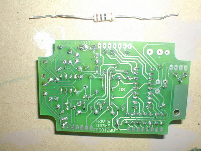
Latest on the speed alert. I have received the kit and after a bit of soldering practice started to build the boards. However.... there is a resistor to mount and the wires from the resistor are too thick to go through the holes on the PCB. Most of the resistors have quite thin wires and don't present a problem and the board does have holes of differing diameters - it's just that the holes provided for this resistor which is bigger than the others are the small size. Can any electronically skilled person tell me whether it is ok to open up the holes in the PCB and if so what is the best way to do it. Obviously I dont want to damage this purpose made board.
Ron
Posted: Sun Feb 10, 2008 4:44 pm
by moonshine
Without seeing the back of the board it is very difficult to say. However, I can't see any problem with opening up the holes using a very fine drill, as long as there is sufficient space between the tracks on the circuit board to allow you to do so without infringing on an adjacent track.
Posted: Sun Feb 10, 2008 5:21 pm
by ronhud
Thanks moonshine. Photo below. One leg of the resistor goes into the hole at the top right corner (next to the one with the + sign). The other leg goes into the hole immediately below it. Even the smallest drill I have and it is v small is bigger than I feel comfortable with. One thing I'm a bit concerned about is the pad of metal round the hole might be torn away by the flute of the drill. I've tentatively tried pushing away with the tip of a bradawl hoping that I might sort of squeeze it a bit wider but no luck! The kit came from a co in Australia and I've emailed them re the problem but I would prefer to get on with it now if I can. It may be a simple solution like getting a resistor with thinner legs but in spite of googling I've had little success in finding suppliers to approach.
Maplins do resistors but I would be better taking the board in somewhere so that I cn be sure I get the right part.
Ron
[/img]
Posted: Sun Feb 10, 2008 11:32 pm
by The Great Pretender
Electronics and me dont mix

but the colour coding on it will tell them all they need to know..........i think.
Instead of trying to open up the holes why not reduce the wire size, file or emery it?
Posted: Sun Feb 10, 2008 11:33 pm
by moonshine
Looks to me that there is plenty of room to enlarge the holes. You will only need a drill fractionally bigger than the existing hole. Don't drill from the top of the board, or when the drill breaks through you may dislodge the track. Drill carefully from the underside of the board (where the tracks are) and you should be fine.
In the very unlikely event that you do dislodge the pad or track, you could easily repair it by carefully soldering some fine tinned copper wire along the track.
Pity you're not a bit closer, as I would gladly do it for you.