


Hi Guys,
quick question but I had a flashing HOLD light the other day.it hasn't happened again since but I wanted to read the fault code from the diags connector. Mines a 95 bongo.
In short, I don't seem to have a FEN terminal..so got a bit confused with the service manual anyhow, I did a bit of googling and found that to read the Auto Transmission faults, short TAT and GND, then read from B+ and FAT...from which I got
1 Long deflection followed by 7, then another 7 repeating...
Is the 1 Long deflection a 10, or just an indicator to say there is a fault code to follow ? (i.e is this error 17, then loads of error 7 codes, or just error 7 ..and any ideas what that means....service manual suggests 17 is a speed meter sensor 2 ...but that is I assume for the codes you'd read off FEN...which I don't have....
thanks,
Ant.
Diagnostic Connector with VoltMeter
Moderators: Doone, westonwarrior
Diagnostic Connector with VoltMeter
1995 M reg 2WD AFT in green/grey (and an Oakley Thermonuclear Protection decal for some reason!)
-
g8dhe

- Supreme Being
- Posts: 10222
- Joined: Sun Apr 13, 2008 10:06 pm
- Location: Worthing, West Sussex.
- Contact:
Re: Diagnostic Connector with VoltMeter
I've always understood from this site http://www.philmcfadden.co.uk/MazdaDiagnosticBox.htm
that the Long pulses are the Tens so ONE long pulse is 10+, TWO long pulses are 20+ etc
You suggest however that your NOT seeing the LONG pulse repeated ?
that the Long pulses are the Tens so ONE long pulse is 10+, TWO long pulses are 20+ etc
So yours would be 17, assuming you see 1 LONG pulse, pause, 7 SHORT. This should then repeat 1 LONG pulse, pause, 7 SHORT.The first series of long flashes (1.2 Secs) are the tens position. There is a short pause (1.6 Secs) and then the second series of quick flashes (0.4 Secs) begins which are the digits. The codes are repeated indefinitely.
Example: ------ ------ (2) -- -- -- (3) is 23 – RH 02 Sensor
You suggest however that your NOT seeing the LONG pulse repeated ?
 Spherical Visions
Re: Diagnostic Connector with VoltMeter
right...so I did it again and noticed the HOLD light flashes the same pulses as I'm reading off the voltmeter between FAT/B+
So heres what I do
Short TAT/GND (I'm an auto gearbox)
I pulled the voltmeter leads off so nothing connected to FAT/B+
Turn ignition on and HOLD light lights up for about 3 seconds, then flashes 7 times....3 second gap....7 flashes..3 second gap...7 flashes....
So I think that's a fault code 7....but can't find any reference to that (my service manual says 7 is a speed meter sensor 2 but I'm not sure what the O next to glowplug and HOLD means in that table)
1995 M reg 2WD AFT in green/grey (and an Oakley Thermonuclear Protection decal for some reason!)
-
g8dhe
- Supreme Being
- Posts: 10222
- Joined: Sun Apr 13, 2008 10:06 pm
- Location: Worthing, West Sussex.
- Contact:
Re: Diagnostic Connector with VoltMeter
Yup, code 7 does refer to the Vehicle Speed Sensor.
I think that 21-5H2, perhaps someone else can confirm ?
http://lushprojects.com/bongopartsmk2/c ... 03.html#67
I think that 21-5H2, perhaps someone else can confirm ?
http://lushprojects.com/bongopartsmk2/c ... 03.html#67
Re: Diagnostic Connector with VoltMeter
thanks mate...I notice that code 6 is 'Speed Meter Sensor 1 (Revolution Sensor)' and code 7 is 'Speed Meter Sensor 2 (Speed Meter Sensor)' ...is that one you tagged, covered by both error codes or could it be an alternative sensor somewhere ?
1995 M reg 2WD AFT in green/grey (and an Oakley Thermonuclear Protection decal for some reason!)
-
g8dhe
- Supreme Being
- Posts: 10222
- Joined: Sun Apr 13, 2008 10:06 pm
- Location: Worthing, West Sussex.
- Contact:
Re: Diagnostic Connector with VoltMeter
I think that the Speed Sensor (6) is the RPM of the engine,
whilst Vehicle Speed (7) is the output shaft from the gearbox which relates to road speed,
but I have a V6 which is a bit different! I'm sure one of the others will be along to confirm or otherwise, I do recall that is has been discussed several times a search might find the relevant post but i'm on a tablet at the moment which does help!
-
Northern Bongolow

- Supreme Being
- Posts: 7713
- Joined: Mon Mar 15, 2010 11:33 pm
- Location: AKA Vanessa
Re: Diagnostic Connector with VoltMeter
black dial on top of the fuel pump, throttle position sensor, seems to give grief like this, remember where it is and loosen and turn a little, best to mark it first.
Re: Diagnostic Connector with VoltMeter
cheers, I'll give the throttle position sensor a tweek and clear the fault code..see if it returns. I'm not seeing any funny business on the speedo and when the hold light was flashing it didn't seem to have trouble changing gears so wasn't convinced it was in a limp mode...the next day it was a little worried it was staying in a low gear but think I was just paranoid...it was a pretty cold day and the cold engine....
cheers,
Ant.
cheers,
Ant.
1995 M reg 2WD AFT in green/grey (and an Oakley Thermonuclear Protection decal for some reason!)
-
Simon Jones

- Supreme Being
- Posts: 9341
- Joined: Mon Aug 29, 2005 3:34 pm
- Location: Salisbury (ish), Wiltshire
Re: Diagnostic Connector with VoltMeter
Just a thought: have you checked the condition and level of th ATF? Low level may affect ability to change gear.
Re: Diagnostic Connector with VoltMeter
thanks...ATF seemed ok..checked whilst running (but not in gear at the time) was pink/clear and in the vague vicinity of the full mark as opposed to the low mark (doesn't seem particularly easy to take a reading however !).
Reading around ford ranger forums etc...I think Geoff's correct above...the 07 code refers to the "Speed Sensor 2" as per my bongo service manual and that appears to be a sensor on the output of the transmission. I read somewhere that if that fails, the ECU uses Speed Sensor 1 as a backup which could be why I haven't really seen any driving issues or funny business on the speedo. I'll see if I can get the sensor out to test with a magnet...failing that, anyone know the resistance it should normally read ? Rather annoying the service manual glosses over this sensor ...just shows the connector for the speedometer sensor in my book but not where it plugs into so I'll look where Geoff pointed at and see if I can fiddle with it !
I did try testing the output of the Throttle Position Sensor as weel..couldn't get any volts from back testing the Orange/White 2I pin on the ECU whether the throttle was closed or open...and couldn't get my probe into the contacts on the sensor body or plug either...anyone any experience testing the resistance ? I could just unplug the sensor and test the contacts without the need for power then....either that or use a pin/paperclip !
thanks,
Ant.
1995 M reg 2WD AFT in green/grey (and an Oakley Thermonuclear Protection decal for some reason!)
-
Driver+Passengers
- Supreme Being
- Posts: 2019
- Joined: Mon Mar 14, 2011 1:56 pm
- Location: Fife
Re: Diagnostic Connector with VoltMeter
I believe you have to have the ign at I or II - can't remember the colour off the of my head, but I've soldered a sensor wire to the TPS pin at the ECU end of the harness.cookan wrote:I did try testing the output of the Throttle Position Sensor as weel..couldn't get any volts from back testing the Orange/White 2I pin on the ECU whether the throttle was closed or open...and couldn't get my probe into the contacts on the sensor body or plug either...anyone any experience testing the resistance ? I could just unplug the sensor and test the contacts without the need for power then....either that or use a pin/paperclip !
Edit: mine measures something in the region of 3-6V, but differs slightly depending on whether the engine is running or not.

What she doesn't know won't hurt me.
-
g8dhe
- Supreme Being
- Posts: 10222
- Joined: Sun Apr 13, 2008 10:06 pm
- Location: Worthing, West Sussex.
- Contact:
Re: Diagnostic Connector with VoltMeter
The voltages are here http://www.igmaynard.co.uk/bongo/forum/ ... 87#p139787
and the resistance is discussed here http://www.igmaynard.co.uk/bongo/forum/ ... =3&t=14201 , read the WHOLE thread looks like the manual might have a printing error!
and the resistance is discussed here http://www.igmaynard.co.uk/bongo/forum/ ... =3&t=14201 , read the WHOLE thread looks like the manual might have a printing error!
Re: Diagnostic Connector with VoltMeter
cheers guys, interesting threads..found the speed sensor now I think...just above a big puddle of water from the weekends rain so I'll look for somewhere dry to park up before I go fiddling there  I'll test as per the other threads tomorrow and see what I get on the TPS as well.
1995 M reg 2WD AFT in green/grey (and an Oakley Thermonuclear Protection decal for some reason!)
Re: Diagnostic Connector with VoltMeter
right...throttle position sensor wasn't giving a reading yesterday at the ECU..so this morning I plugged it up before driving the kids to school......it all of a sudden started to read by the time I got to the end of my drive..it then read up and down all the way to school and back...so maybe I have a sticky TPS, Just to confirm, I do get a reading with the ignition in the ON position without needing to start the car up so this thing can be tested with full throttle without annoying the neighbours! In fact, I was getting 1.17 closed and 4.1 open so I tweeked the TPS a little and managed to get it reading 1.3 closed and 4.21 open so pretty chuffed with myself for hitting the specification and that also justified the fluke I bought a few months back Wonder if that will help my 2-3 second lumpy startup on cold mornings...we'll see tomorrow.
Now..back to the Speed Sensor 2 / error code 7...I'm wondering whether Speed Sensor 2 is actually the engine revs as opposed to the transmission output..reason being, the service manual says the test condition for Speed Sensor 2 (ECU Pin 2E on automatics) is with Ignitions ON/OFF or at Idle ....whereas the test condition for Speed Sensor 1 is with Ignition ON or At Driving over 25km/h..that says to me Sensor 1 is the transmission, and sensor 2 is engine.
Either way, I was getting about 4.7V with ig ON (which appears in range), but then 11.8v at Idle rising to 12v when reving the engine which is way off what the manual says (2-3v).
could this indicate a faulty kph-mph chip or does this signal come directly from the sensor (and can anyone point me to it!).
thanks,
Ant.
1995 M reg 2WD AFT in green/grey (and an Oakley Thermonuclear Protection decal for some reason!)
-
g8dhe
- Supreme Being
- Posts: 10222
- Joined: Sun Apr 13, 2008 10:06 pm
- Location: Worthing, West Sussex.
- Contact:
Re: Diagnostic Connector with VoltMeter
The sensor that drives the Speedo itself is the road speed one on the output shaft, that sends pulses suitable for Km/Hr, if a chip has been fitted then normally its on the back of the display (4 leads - power and a pair that intercept the sensor signal) and drives the Speedo - the Speedo then sends the signal on to the ECU and a dozen other places its needed.
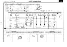
The sensor is the on C1-03, that feeds the square box which is the Speedo, this then sends the signal out on connector 1D to the other places.
The sensor is the on C1-03, that feeds the square box which is the Speedo, this then sends the signal out on connector 1D to the other places.