


coolant flow - (follow up to cooling diagram)
Moderators: Doone, westonwarrior
-
missfixit70

- Supreme Being
- Posts: 12431
- Joined: Fri Jun 01, 2007 3:53 pm
- Location: weymouth
Re: coolant flow - (follow up to cooling diagram)
I reckon by the time it's got to point of possibly sticking the stat open, chances are the damage is already done.
You can't polish a turd - but you can roll it in glitter.
Re: coolant flow - (follow up to cooling diagram)
Please don't try this at home Kidswiddowson2008 wrote:Test 13-12-09 - (Abusive testing)widdowson2008 wrote:
Stat in an over run position at 8.5mm stroke
It would appear that the above diagram is exactly what happens in reality with the exception that I pushed it 1.5mm more than the diagram.
stat in housing clamped to bench
heated via port with Bosch blower heater (probably classified as excessive to the point of abuse)
hissing sound – possibly wax escaping – ie: reached end of possible stroke
5mm over-run recorded (3.5mm on drawing) ie: disc came into contact with bypass port with 5mm more stroke to go
Stat remained ‘stuck’ in this position ie: Open, but sprung back when gently persuaded. - This suggested that the stat CAN in fact get stuck in the OPEN state when subjected to excessive temperatures
Will try again to see if it still works after this harsh treatment

-
widdowson2008

- Supreme Being
- Posts: 1703
- Joined: Tue Nov 18, 2008 10:15 pm
- Location: N.E.Derbyshire
Re: coolant flow - (follow up to cooling diagram)
Well, it still worked (after a fashion) - however, sad to say, I finished up taking it completely to bits!! with one more part to face really excessive heat tomorrow - the wax cylinder (cos I think that may break down even further)rita wrote:widdowson2008 wrote:Please don't try this at home Kidswiddowson2008 wrote:
Will try again to see if it still works after this harsh treatment
And if the heat don't crack it, then its THE SAW
Have a guess how many individual parts there are in a simple thermostat (not including the wax.)
....and Rita - don't let the kids watch tomorrow
Steve
-
widdowson2008
- Supreme Being
- Posts: 1703
- Joined: Tue Nov 18, 2008 10:15 pm
- Location: N.E.Derbyshire
Re: coolant flow - (follow up to cooling diagram)
From this - stat after attack with angle grinder cos saw wouldn't look at it

to this - what the stat looks like inside

Opening temp tests tomorrow - with data (hopefully)
to this - what the stat looks like inside
Opening temp tests tomorrow - with data (hopefully)
Last edited by widdowson2008 on Thu Dec 17, 2009 2:07 pm, edited 1 time in total.
Steve
-
dandywarhol

- Supreme Being
- Posts: 5446
- Joined: Mon Dec 19, 2005 10:18 pm
- Location: Edinburgh
Re: coolant flow - (follow up to cooling diagram)
Looks like the bypass spring allows the bypass disc (valve) to close against the housing to form a seal as the stat keeps opening as temp rises 

Whale oil beef hooked
Renault Lunar Telstar
Yamaha TD1C 250, Merc SLK200, KTM Duke 690
Renault Lunar Telstar
Yamaha TD1C 250, Merc SLK200, KTM Duke 690
-
widdowson2008
- Supreme Being
- Posts: 1703
- Joined: Tue Nov 18, 2008 10:15 pm
- Location: N.E.Derbyshire
Re: coolant flow - (follow up to cooling diagram)
Exactly what happens IMHO. I was going to do accurate heat tests today logging temperature/valve travel just using the stat.dandywarhol wrote:Looks like the bypass spring allows the bypass disc (valve) to close against the housing to form a seal as the stat keeps opening as temp rises
However, because you have brought this up, I am now going to split the housing and mount the stat in the housing so that the relationship I have shown on paper can be physically seen (and photographed)
Think about it. If there were no second spring, and the bypass disc were rigidly fixed to the valve stem (no circlip), then as the valve assembly reached the bypass and closed it off, what would happen?
The wax would continue to expand, but because its only relief is the valve movement (and this has now stopped moving), the result will be a pressure build up in the wax chamber. As this is effectively a hydraulic situation, there will be no (or very little) compression of the wax - it will just keep expanding, which will result in a ruptured cylinder.
Thats my thinking and its my belief that this is the ONLY function of the bypass spring.
The test will hopefully show this beyond doubt - one way or the other.
Incidentally dandy, you need to take a look at the latest drawing cos it is slightly different. I had to ammend it following physical dissection of the stat for accurate vernier calliper measurement.
Steve
-
Grahame at work
- Bongolier
- Posts: 330
- Joined: Fri Sep 30, 2005 12:43 pm
- Location: Aberdeen
Re: coolant flow - (follow up to cooling diagram)
This is great stuff - I agree with what you are coming up with - wish I had time to do this sort of thing  far more interesting than what I normally get to do.
Will be really interesting to find out what is where when you hit 95C.
keep up the good work.
Regards grahame
Will be really interesting to find out what is where when you hit 95C.
keep up the good work.
Regards grahame
Joanie2 has had a sex change and is remaned Bert
-
widdowson2008
- Supreme Being
- Posts: 1703
- Joined: Tue Nov 18, 2008 10:15 pm
- Location: N.E.Derbyshire
Re: coolant flow - (follow up to cooling diagram)
One of the joys of being retired (ish).Grahame at work wrote:This is great stuff - I agree with what you are coming up with - wish I had time to do this sort of thing
Will be really interesting to find out what is where when you hit 95C.
keep up the good work.
Regards grahame
Some years ago, I was dreading retirement - wondered what I would do.
Not so now - not enough hours in a day to do what I want.
Steve
-
widdowson2008
- Supreme Being
- Posts: 1703
- Joined: Tue Nov 18, 2008 10:15 pm
- Location: N.E.Derbyshire
Re: coolant flow - (follow up to cooling diagram)
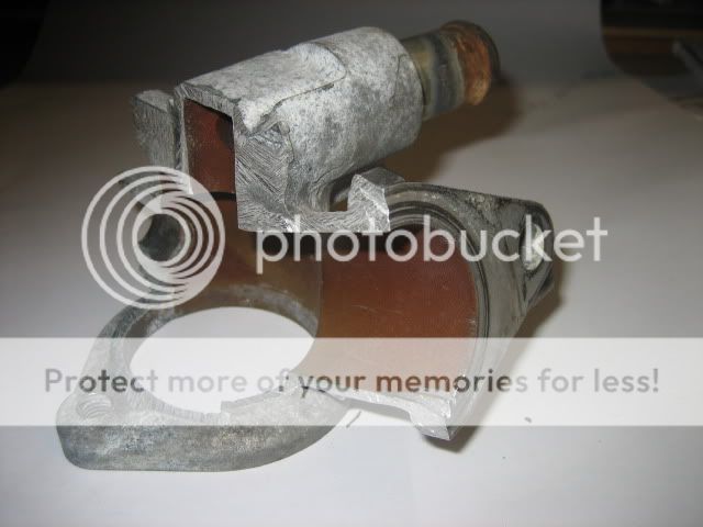
Step closer to rig setup - Stat in cutaway housing. (  sorry Bongo for hacking one of your bits, but I needed to know)

Steve
-
dandywarhol
- Supreme Being
- Posts: 5446
- Joined: Mon Dec 19, 2005 10:18 pm
- Location: Edinburgh
Re: coolant flow - (follow up to cooling diagram)
Quite a small apeture for the bypass to flow through - good work - now you need to paint the cut away red and frame it 
The 8mm of stat travel should certainly seal off the bypass...................
The 8mm of stat travel should certainly seal off the bypass...................
Whale oil beef hooked
Renault Lunar Telstar
Yamaha TD1C 250, Merc SLK200, KTM Duke 690
Renault Lunar Telstar
Yamaha TD1C 250, Merc SLK200, KTM Duke 690
-
The Great Pretender

- Supreme Being
- Posts: 2671
- Joined: Thu Oct 19, 2006 10:10 pm
- Location: Wigan
Re: coolant flow - (follow up to cooling diagram)
Isn't the head bypass on the missing piece?dandywarhol wrote:Quite a small apeture for the bypass to flow through - good work - now you need to paint the cut away red and frame it
The 8mm of stat travel should certainly seal off the bypass...................
To infinity and beyond
-
widdowson2008
- Supreme Being
- Posts: 1703
- Joined: Tue Nov 18, 2008 10:15 pm
- Location: N.E.Derbyshire
Re: coolant flow - (follow up to cooling diagram)
Hi MelThe Great Pretender wrote:Isn't the head bypass on the missing piece?dandywarhol wrote:Quite a small apeture for the bypass to flow through - good work - now you need to paint the cut away red and frame it
The 8mm of stat travel should certainly seal off the bypass...................
No, none of the ports are missing.
The one to the left is from the heater/expansion tank
The one to the right (largest port - flanged) is to the cylinder block
The one directly above the thermostat (full circle-smallest port) is from the head (bypass)
The bottom one (flanged - in my hand) is from the radiator bottom connection
Steve
-
stilldesperate

- Tribal Elder
- Posts: 904
- Joined: Wed Feb 22, 2006 5:00 pm
- Location: Di hard
- Contact:
Re: coolant flow - (follow up to cooling diagram)
Hi Steve,
Are you holding it the way it's seen from the passenger door?
(Just need to get it into perspective).
SD
Are you holding it the way it's seen from the passenger door?
(Just need to get it into perspective).
SD
"The older I get, the faster I was"

-
widdowson2008
- Supreme Being
- Posts: 1703
- Joined: Tue Nov 18, 2008 10:15 pm
- Location: N.E.Derbyshire
Re: coolant flow - (follow up to cooling diagram)
No mate. As seen if you were sat in the back looking at the windscreen.stilldesperate wrote:Hi Steve,
Are you holding it the way it's seen from the passenger door?
(Just need to get it into perspective).
SD
The right hand port bolts onto the engine and the left hand port is from the heaters.
Do these help?
Done

Steve
-
The Great Pretender
- Supreme Being
- Posts: 2671
- Joined: Thu Oct 19, 2006 10:10 pm
- Location: Wigan
Re: coolant flow - (follow up to cooling diagram)
Had me fooled there Steve........... 

Can we have a pic of the missing bit?
Can we have a pic of the missing bit?
To infinity and beyond