coolant flow - (follow up to cooling diagram)

Technical questions and answers about the Mazda Bongo

Moderators: Doone, westonwarrior

User avatar
widdowson2008
Supreme Being
Posts: 1703
Joined: Tue Nov 18, 2008 10:15 pm
Location: N.E.Derbyshire

Re: coolant flow - (follow up to cooling diagram)

Post by widdowson2008 » Sun Dec 06, 2009 3:04 am

Air flow past Bongo when in motion (Bongo that is)
One of the drawings that is going in the fact sheet to assist with cooling system.
Well, its not so much of a fact sheet ........ its turned into a book.

Image
Steve
User avatar
mikeonb4c
Supreme Being
Posts: 22877
Joined: Sun Nov 05, 2006 10:49 pm
Location: Living with Mango Bongo in the North West but with a tendency to roam
Contact:

Re: coolant flow - (follow up to cooling diagram)

Post by mikeonb4c » Sun Dec 06, 2009 10:46 am

widdowson2008 wrote:Air flow past Bongo when in motion (Bongo that is)
One of the drawings that is going in the fact sheet to assist with cooling system.
Well, its not so much of a fact sheet ........ its turned into a book.

Image
Anoher useful drawing. =D>

Some people have been on here to ask whether the underbody cover is necessary. Reasons for it being there have generally been given as protecting engine from dirt and grime, and reducing noise from engine compartment. Its good that this other (possible) function is being promoted. I've not studied theBongo underside to see how well the air scoop theory holds up, but I suspect it is a component in encouraging airflow over the engine block, especially when the scavenger fan is being used.

It would be worth having the airflow arrows show how air enters AND exits the compartment, as well as showing the scavenger fan position and angle of mounting as that would help explain what goes on. 8)
User avatar
widdowson2008
Supreme Being
Posts: 1703
Joined: Tue Nov 18, 2008 10:15 pm
Location: N.E.Derbyshire

Re: coolant flow - (follow up to cooling diagram)

Post by widdowson2008 » Sun Dec 06, 2009 2:31 pm

mikeonb4c wrote:
widdowson2008 wrote:Air flow past Bongo when in motion (Bongo that is)
One of the drawings that is going in the fact sheet to assist with cooling system.
Well, its not so much of a fact sheet ........ its turned into a book.

Image
Anoher useful drawing. =D>

Some people have been on here to ask whether the underbody cover is necessary. Reasons for it being there have generally been given as protecting engine from dirt and grime, and reducing noise from engine compartment. Its good that this other (possible) function is being promoted. I've not studied theBongo underside to see how well the ari scoop theory holds up, but I suspect it is a component in encouraging airflow over the engine block, especially when the scavenger fan is being used.

It would be worth having the airflow arrows show how air enters AND exits the compartment, as well as showing the scavenger fan position and angle of mounting as that would help explain what goes on. 8)
It does protect the engine from all the crap kicked up from the roads, but IMHO, its primary function is to direct the natural flow of air (when moving) and from the scavenger fan (when stopped) up past the engine. If you look at the shape of it, particularly at the front end, you'll see what I mean. Its an AIR SCOOP. The other functions you mention above (again IMHO) are just bonus features.
If it was just a cover, they could have made it a much simpler shape.
Steve
User avatar
mikeonb4c
Supreme Being
Posts: 22877
Joined: Sun Nov 05, 2006 10:49 pm
Location: Living with Mango Bongo in the North West but with a tendency to roam
Contact:

Re: coolant flow - (follow up to cooling diagram)

Post by mikeonb4c » Sun Dec 06, 2009 2:45 pm

widdowson2008 wrote:
mikeonb4c wrote:
widdowson2008 wrote:Air flow past Bongo when in motion (Bongo that is)
One of the drawings that is going in the fact sheet to assist with cooling system.
Well, its not so much of a fact sheet ........ its turned into a book.

Image
Anoher useful drawing. =D>

Some people have been on here to ask whether the underbody cover is necessary. Reasons for it being there have generally been given as protecting engine from dirt and grime, and reducing noise from engine compartment. Its good that this other (possible) function is being promoted. I've not studied theBongo underside to see how well the ari scoop theory holds up, but I suspect it is a component in encouraging airflow over the engine block, especially when the scavenger fan is being used.

It would be worth having the airflow arrows show how air enters AND exits the compartment, as well as showing the scavenger fan position and angle of mounting as that would help explain what goes on. 8)
It does protect the engine from all the crap kicked up from the roads, but IMHO, its primary function is to direct the natural flow of air (when moving) and from the scavenger fan (when stopped) up past the engine. If you look at the shape of it, particularly at the front end, you'll see what I mean. Its an AIR SCOOP. The other functions you mention above (again IMHO) are just bonus features.
If it was just a cover, they could have made it a much simpler shape.
I'm sure you're right. Just need to crawl underneath mine to confirm that hunch. With a little tweaking, the scavenger fan could be used as a charging device when on the move by getting it to windmill (I kid you not) :lol:
User avatar
widdowson2008
Supreme Being
Posts: 1703
Joined: Tue Nov 18, 2008 10:15 pm
Location: N.E.Derbyshire

Re: coolant flow - (follow up to cooling diagram)

Post by widdowson2008 » Sun Dec 06, 2009 4:16 pm

mikeonb4c wrote:[quote="widdowson2008
Image
Anoher useful drawing. =D>

Some people have been on........................theory holds up, but I suspect it is a component in encouraging airflow over the engine block, especially when the scavenger fan is being used.

It would be worth having the airflow arrows show how air enters AND exits the compartment, as well as showing the scavenger fan position and angle of mounting as that would help explain what goes on. 8)[/quote]

Mike

I have changed my thinking after a trip to look up Bongos skirts. In its current form, the drawing I posted showing the underbody pan was very misleading and I'll re-draw it to something a little nearer reality.

Initially, I did it to indicate that this air flow should be considered as an integral part of the cooling thing - and I still think it should. What I failed to factor into the drawing is the nit pickers. :wink: and long may they prosper.
The next offering will ba a little more factual (less theoretical), and will indeed address your earlier very VALID comments ..'It would be worth having the airflow arrows show how air enters AND exits the compartment
Steve
User avatar
widdowson2008
Supreme Being
Posts: 1703
Joined: Tue Nov 18, 2008 10:15 pm
Location: N.E.Derbyshire

Re: coolant flow - (follow up to cooling diagram)

Post by widdowson2008 » Sun Dec 06, 2009 5:42 pm

For the benefit of all, and the sharp eyed Irishman who spotted the deliberate error :^o :^o :^o :^o :^o
here is an update.
Does this portray what you were describing Mike?
Image
Steve
User avatar
mikeonb4c
Supreme Being
Posts: 22877
Joined: Sun Nov 05, 2006 10:49 pm
Location: Living with Mango Bongo in the North West but with a tendency to roam
Contact:

Re: coolant flow - (follow up to cooling diagram)

Post by mikeonb4c » Sun Dec 06, 2009 6:14 pm

Now THAT (at a quick glance) strikes me as spot on. It would make sense too, in design terms, as it helps ensure cooling air is not forced through the compartment unless the system sensors (or the over-ride switch owner :lol: ) deems it necessary. Excellent drawing =D> =D> =D>
User avatar
widdowson2008
Supreme Being
Posts: 1703
Joined: Tue Nov 18, 2008 10:15 pm
Location: N.E.Derbyshire

Re: coolant flow - (follow up to cooling diagram)

Post by widdowson2008 » Sun Dec 06, 2009 6:30 pm

mikeonb4c wrote:Now THAT (at a quick glance) strikes me as spot on. It would make sense too, in design terms, as it helps ensure cooling air is not forced through the compartment unless the system sensors (or the over-ride switch owner :lol: ) deems it necessary. Excellent drawing =D> =D> =D>
Thank you kind sir :oops:

Don't know if you noticed O eagle eyed one, :wink: but the front wheel nuts have actually been put back on the vehicle. (they were missing on the first.) :D

I throw these in from time to time to see if you are paying attention :^o :^o
Steve
User avatar
mikeonb4c
Supreme Being
Posts: 22877
Joined: Sun Nov 05, 2006 10:49 pm
Location: Living with Mango Bongo in the North West but with a tendency to roam
Contact:

Re: coolant flow - (follow up to cooling diagram)

Post by mikeonb4c » Sun Dec 06, 2009 7:07 pm

widdowson2008 wrote:
mikeonb4c wrote:Now THAT (at a quick glance) strikes me as spot on. It would make sense too, in design terms, as it helps ensure cooling air is not forced through the compartment unless the system sensors (or the over-ride switch owner :lol: ) deems it necessary. Excellent drawing =D> =D> =D>
Thank you kind sir :oops:

Don't know if you noticed O eagle eyed one, :wink: but the front wheel nuts have actually been put back on the vehicle. (they were missing on the first.) :D

I throw these in from time to time to see if you are paying attention :^o :^o
Funny you should say that. I did notice the wheels were the std 15" alloys and not bling bling 17" ones like wot DBO, MissF and moi have. I didn't notice your nuts were missing though -didn't like to stare too closely - people might get the wrong idea - I'm sure you know how it is :lol: :lol: :lol:
User avatar
widdowson2008
Supreme Being
Posts: 1703
Joined: Tue Nov 18, 2008 10:15 pm
Location: N.E.Derbyshire

Re: coolant flow - (follow up to cooling diagram)

Post by widdowson2008 » Sun Dec 06, 2009 7:12 pm

mikeonb4c wrote:
widdowson2008 wrote:
mikeonb4c wrote:Now THAT (at a quick glance) strikes me as spot on. It would make sense too, in design terms, as it helps ensure cooling air is not forced through the compartment unless the system sensors (or the over-ride switch owner :lol: ) deems it necessary. Excellent drawing =D> =D> =D>
Thank you kind sir :oops:

Don't know if you noticed O eagle eyed one, :wink: but the front wheel nuts have actually been put back on the vehicle. (they were missing on the first.) :D

I throw these in from time to time to see if you are paying attention :^o :^o
Funny you should say that. I did notice the wheels were the std 15" alloys and not bling bling 17" ones like wot DBO, MissF and moi have. I didn't notice your nuts were missing though -didn't like to stare too closely - people might get the wrong idea - I'm sure you know how it is :lol: :lol: :lol:
Steady on sailor :shock:
Steve
User avatar
dandywarhol
Supreme Being
Posts: 5446
Joined: Mon Dec 19, 2005 10:18 pm
Location: Edinburgh

Re: coolant flow - (follow up to cooling diagram)

Post by dandywarhol » Sun Dec 06, 2009 7:32 pm

I'm glad the wheel nuts are on - but how does one get into said vehicle?
Whale oil beef hooked
Renault Lunar Telstar
Yamaha TD1C 250, Merc SLK200, KTM Duke 690
User avatar
widdowson2008
Supreme Being
Posts: 1703
Joined: Tue Nov 18, 2008 10:15 pm
Location: N.E.Derbyshire

Re: coolant flow - (follow up to cooling diagram)

Post by widdowson2008 » Sun Dec 06, 2009 7:41 pm

dandywarhol wrote:I'm glad the wheel nuts are on - but how does one get into said vehicle?
Drivers door dandy, round the other side. :wink:
Steve
User avatar
widdowson2008
Supreme Being
Posts: 1703
Joined: Tue Nov 18, 2008 10:15 pm
Location: N.E.Derbyshire

Re: coolant flow - (follow up to cooling diagram)

Post by widdowson2008 » Mon Dec 07, 2009 8:27 pm

ooooooops :oops:
Just learned that if you delete pics from photobucket, they disappear from the post - Sorry :oops:

This is a simlar one to the one deleted
Image
Steve
User avatar
widdowson2008
Supreme Being
Posts: 1703
Joined: Tue Nov 18, 2008 10:15 pm
Location: N.E.Derbyshire

Re: coolant flow - (follow up to cooling diagram)

Post by widdowson2008 » Sat Dec 12, 2009 10:02 am

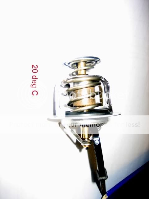
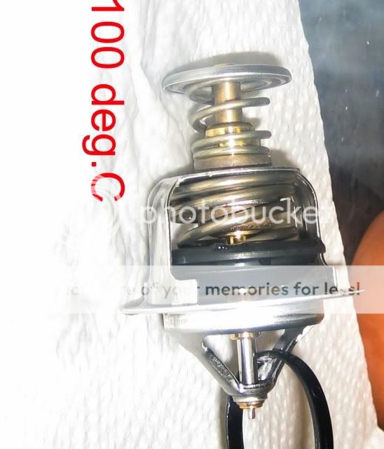
For those interested in what the thermostat looks like in bits
Image

The component named SPRING RETAINING CAP is actually the BYPASS VALVE as well as the spring retaining cap
You may notice that the spring is tapered - bigger at the valve end.
The other spring is also tapered.

and Initial operational pics - 20 deg C and 100 deg C - Wads more testing to do when housing arrives
Image
Image

Note: at 100 deg C, the travel of the valve is 11mm. (8.5mm stated in manual) This is because in the photograph, the travel is NOT restrained by the bypass as it would be when in situ in the Bongo.

As you may have gathered, I'm not just looking at the internals, I'm taking the internals to bits. Sad eh?

Dissection continues :evil: :evil:
Steve
User avatar
mikeonb4c
Supreme Being
Posts: 22877
Joined: Sun Nov 05, 2006 10:49 pm
Location: Living with Mango Bongo in the North West but with a tendency to roam
Contact:

Re: coolant flow - (follow up to cooling diagram)

Post by mikeonb4c » Sat Dec 12, 2009 10:28 am

Not sad at all - it will be very interesting to hear your conclusion on how this thing works and your thoughts on what kind of things are likely to cause it to fail, either due to component failure or as a result of some other effect like build up of hard deposit or w.h.y. 8)

Its sad though that my 1st instinct after showering and dressing is not breakfast, but logging on here and getting sucked in to posting. I need treatment I do :lol: :lol: :lol:
Locked

Return to “Techie Stuff”